
- Offer Profile
- Adelaide Robotics Research Group
The Adelaide Robotics Research Group was formed in 2002 to further research into robotics at the University of Adelaide. Areas which are of particular interest to the group include micro-motion manipulators, robotic measurement systems, mobile robotics and the modelling of insects through robotics.
Micro Air Vehicle
- The aim of this honours project was to design, build
and fly a micro air vehicle with flapping wing mechanism. The vehicle should
be as small and light as possible with a low cruising speed. It is
anticipated that the aircraft will be propelled by one or more electric
motors and be controlled using a radio control system.
(Maziar Arjomandi, Richard Kelso, Craig Michael Gerrard, Richard Hillan, Matthieu Richard Nelson and Mathew Thomas Ward)
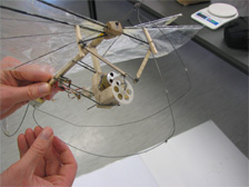
DragonFly - Close up
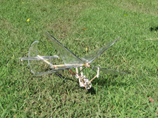
DragonFly - Landed on Gras
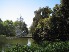
DragonFly - Flying over the river Torrens
Search and rescue UAV
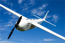
- This honours project involves the design and
construction of an autonomous Unmanned Aerial Vehicle (UAV). The aircraft
has been designed for civil applications such as surveillance or search and
rescue missions by incorporating imaging equipment and payload deployment
capabilities.
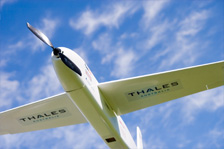
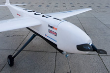
The multipurpose platform has been configured to take part in the Australian Research Centre for Aerospace Automation’s UAV Outback Challenge to be held in Queensland in September, 2007. For successful entry into this challenge, the UAV must demonstrate the ability to locate and assist a human lost in the Australian outback. A broad study of similar UAVs indicated a conventional design was most suitable for the platform.
The aircraft is manufactured primarily from composite materials using a female mould process. The wings, spanning two metres have a foam core with carbon fibre spars. An electric power plant delivering 4 kilograms of static thrust powers the aircraft with a predicted maximum speed of 120km/hr and an endurance of one hour. The control system incorporates a Micropilot 2028 autopilot enabling autonomous flight and remote communication over a range of 10 kilometres. An analogue camera, mounted in the rear of the aircraft will stream images over a 10 kilometre range with 450 TV lines and a 70 degree field of view.
Testing has been conducted for a parachute recovery system and a descent rate of 5.5 m/s is expected. When launched from a car the aircraft will also be capable of deploying a 600 gram payload.(Maziar Arjomandi, Nayan Uday Avalakki, Jonathan Bannister, Benjamin John J. Chartier, Travis Mark Downie, Brad Alexander A. Gibson, Crystal Rhiannon Gottwald, Peter Ian Moncrieff and Michael Scott Williams)
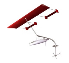
Wing Borne HydroFoil (WBHF)
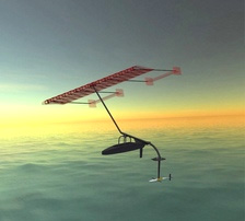
- The Wingborne Hydrofoil (WBHF) is a high performance
marine craft, conceptualised and developed theoretically by Mr. Stephen
Bourn. In 2007 undergraduate students commenced a project with the aim to
design and manufacture a fullscale functional prototype of a 'Wing-Borne
Hydrofoil'. The basis of this design differs from the majority of high-speed
sailing craft in that it utilises a wing rather than a conventional sail.
The ability of the wing to adjust to the optimal angle relative to the wind
gives the WBHF the capability to tack (and hence sail) both upwind and
downwind. Furthermore by tacking the craft downwind the craft is able to
sail faster than the wind. Another distinguishing feature of the WBHF is its
ability to lift the hull out of the water when the craft achieves sufficient
velocity, thus eliminating a significant source of drag, and hence
accelerating the craft to considerably high speeds. Other design features
that contribute to the high performance and safety of the craft include the
ability to self-correct and stabilise when the craft becomes unbalanced, the
quick release of the wing, customized hydrofoil design suited exclusively to
this application and lightweight design of the craft, attained using
non-conventional materials and manufacturing methods. The craft employs
several control systems to ensure stability once flight is achieved and also
provide pilot control. Given these unique characteristics, it is believed
the WBHF has the potential to challenge several sailing records including
the bi-directional nautical mile sailing speed record and ultimately the
world sailing speed record.
(Ben S. Cazzolato, Carl Q. Howard, Danya J. Cheng, Keith Robert R. Crouch, Thomas James Hill, Joshua Johannes Holmes, Ashok Athreya Kaniyal, Antoni Alexander Kourakis, Heath Andrew Nankivell, Benjamin Andrew Ford Newbery, Luke Joseph Rogers and Zhi Qiu Xia)
Wing Borne HydroFoil (WBHF)
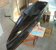
Hull sections joined
- Two carbon fibre halves being joined.
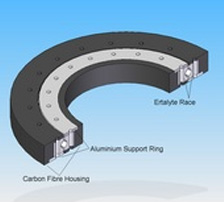
Bearing section view
- Bearings used in coupling main beam to hull and outrigger float.
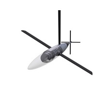
Whole Craft
Bulb clear
- Assembly view of the hydrofoil bulb with transparent mid-section and nose cone.
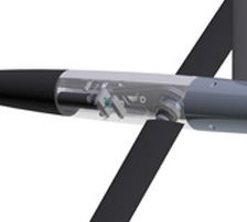
Bulb cutaway
- Cut-away view of the hydrofoil bulb mid-section.
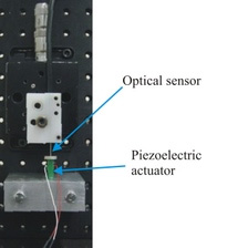
Structure and Control Optimisation for Compliant Micromotion Manipulator
- The current research is aimed to design a new
micromanipulation system to provide micro/nano motion for such as performing
intracytoplasmic sperm injection. This is a procedure used in
invitro-fertilisation where a human egg is injected with sperm. This project
uses piezoelectric actuators and a novel compliant mechanism in order to
achieve ultra fine-motion. This current work is focused on the field of
compliant mechanism research, and involves study of a particular topology of
mechanism that provides 3 planar degrees of freedom.
(Daniel Handley)
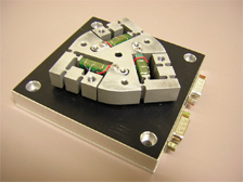
Front view
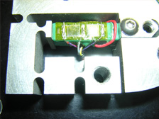
Detail
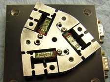
Top view
Development of robot understanding
- This research project attempts to undertake the task
of developing and demonstrating robotic understanding. This is an extension
of robotic learning implemented via a simplistic thought process and memory
structure. The result of the project will be a visual thought process that
shows robot's thought process and how the robot is able to use its past
experiences to demonstrate its understanding of concepts.
(Ben Longstaff and Tien-Fu Lu)
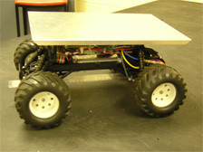
Side view
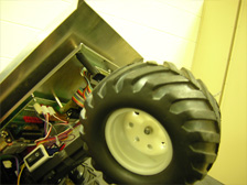
The wheel
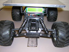
Suspension
Modeling of Compliant Micro-motion Stages with Flexure Hinges
- This research project focuses on the methodology of
deriving simple but effective kinematic and static models of compliant
micro-motion stages which accurately represent the real system. The models
will benefit the design and optimisation processes where a few micro-motion
stage designs can be analysed quickly without the needs of using any
commercially available finite-element software. A 3-DOF micro-motion stage,
which is designed for the positioning of samples in a
Scanning-Electron-Microscope (SEM), is selected as an example to develop
this methodology.
(Yuen Kuan Yong and Tien-Fu Lu)

Prototype 1: Top View
Prototype 2: Top View
Prototype 2 and microscope
Pneumatic Hand
- The School of Mechanical Engineering has been
developing air-muscles since 2004. These have been used in a number of
honours projects such as Stumpy: A Pneumatic Muscle Actuated Bi-pedal Robot.
This project aims to build a fully functional pneumatic prosthetic that is
low weight and has fast response times.
(George Osborne)
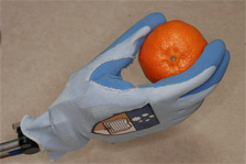
Mandarin
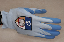
Hand with glove
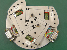
Design of an autonomous mobile robot for experiments on multi-agent systems
- The aim of this honours project is the design and
construction of a fully autonomous mobile robot as a flexible platform for
research in the area of robotic multi-agent systems and artificial
intelligence. The robot will be designed in conformity with the regulations
for the MiddleSize League (MSL, F-2000) of the international robotic soccer
competition "RoboCup". Using RoboCup as test-bed, the project aims at
developing new control strategies for collaborating multi-agent systems of
autonomous mobile robots in a complex and dynamic environment. It is planned
to build a competitive team which could enter the 9th RoboCup world
championships in 2005.
This project has been launched in 2004. Students from Mechatronics, Mechanical Engineering, Computer Science and Electrical and Electronics Engineering have since been working as part of a faculty wide team.(Frank Wornle)
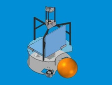
Autonomous mobile robot
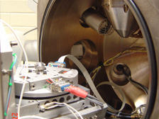
Development of a Stereo Vision and Multiple Laser Stripes based Robotics Measuring System for 3D large surface Profile Acquisition
- The aim of this research project is to develop a
Robotic Measuring System (RMS) which is used for large surface 3D data
acquisition. Normally acquiring three-dimensional surface data can be
achieved with precision by use of touch probes. However, computer vision and
image processing is faster, especially for extracting a large amount of 3D
data such as free-form surface features. The RMS integrates an industrial
robot, a set of CCD camera, a laser stripe projector, and a personal
computer with appropriate software to perform a large surface measuring
task. Topics such as robot calibration, camera calibration, and measurement
strategies are to be investigated.
(Jingsyan Torng)
Soccer Server - Artificial Intelligence (AI) for soccer playing mobile robots
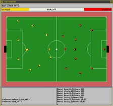
- Every year since 1997, researchers from different
countries have gathered to compete in the world championships of robotic
soccer. The event has drawn a substantial amount of interest from both
industry as well as the general public. The latest RoboCup world
championship tournament took place in July 2004 in Lisbon (Portugal) with a
total attendance of 224 teams from 34 countries competing for the titles in
more than 5 different disciplines. One of these disciplines is the RoboCup
Soccer Simulation League also known as 'Soccer Server' League.
Soccer Server is an educational tool for research on multi-agent systems and artificial intelligence (AI). It allows two teams of 11 simulated players (autonomous agents) to play soccer against each other. Matches are carried out on a virtual pitch: The so-called 'soccer server' is a system that simulates the environment, i. e. the pitch itself, the wind conditions, the location and the velocity of the ball, reactions to the player's commands, etc. Each individual player is a client program written in C, C++, Java, etc. Communication between server and clients is built upon the socket based protocol UDP/IP. A match can be visualized using special monitor programs.
Soccer Server simulates movements of a ball and players, communicates with clients, and controls a game according to rules. To control a player, the corresponding client program needs to send requests to the server regarding the actions it wants to perform (e.g. kick the ball, turn, run, etc.). The server receives those messages, handles the requests, and updates the environment accordingly. In addition, the server provides all players with sensory information (e.g. visual data regarding the position of the ball, goals, and other players). It is important to mention that the server is a real-time system working with discrete time intervals (or cycles). Each cycle has a specified duration, and actions that need to be executed in a given cycle, must arrive to the server during the right interval. Therefore, slow performance that results in missing acting opportunities has a major impact on the performance of the team.
The reigning world champion of the RoboCup Simulation League (2004) is the team ‘STEP’ of the ElectroPult Plant in Russia. Second and third place went to the University of Dortmund (Germany) and Allameh Helli High School (Iran), respectively. Previous winners included the State Key Laboratory of Intelligent Technology and Systems at TsingHua University in China (2001, 2002), the University of Porto (2000), Carnegie Mellon University (1998, 1999) and Humboldt University (1997).(Frank Wornle)
- Every year since 1997, researchers from different
countries have gathered to compete in the world championships of robotic
soccer. The event has drawn a substantial amount of interest from both
industry as well as the general public. The latest RoboCup world
championship tournament took place in July 2004 in Lisbon (Portugal) with a
total attendance of 224 teams from 34 countries competing for the titles in
more than 5 different disciplines. One of these disciplines is the RoboCup
Soccer Simulation League also known as 'Soccer Server' League.
Human Computer Interface
- Humans communicate with computers in a variety of
different ways (e.g. haptic devices, speech recognition program). Such
interfaces require a hardware device for mediation between the human and the
computer to translate a motion variable to a binary number that the computer
can then process.
A Brain Computer Interface (BCI) is a system that acquires and analyses Electroencephalogram (EEG) signals with the goal of creating a high bandwidth communications channel directly between the brain and the computer. It has been used to navigate mobile robots. It gives disabled people a chance to communicate and navigate. BCI suffers with the issues related to modelling and acquisition of EEG signals. All this affects accuracy of the BCI system. Based on the Electrooculogram (EOG) signals, an eye control method serves the same purpose as the BCI. Compared to the EEG, modelling and recording of the EOG signals is far easier.
A simple experiment has been set up to gain some experience with the technology required to build a reliable HCI system. During this experiment, a variety of signals were picked up using simple tin electrodes. The signals were amplified, digitized and analysed in MATLAB. The experiment aimed at controlling the motion of a small mobile robot and was showcased a the university's open day, 2006.(Jayesh L. Minase and Frank Wornle)
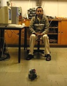
Open day experiment
- During the open day display, a small mobile robot was steered using eye-blink signals.
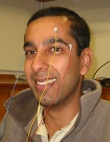
Electrode locations
- Location of electrode to capture signals when eye blinks
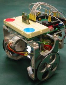
Mobile robot
Dynamic modeling, estimation and control of piezoelectric actuator with application in micro-motion system
- Over the last 30 years numerous micro-motion systems
have been developed to perform a vast range of micro-positioning tasks.
These systems have used different methods to provide fine-accuracy motion.
To provide the finest-accuracy motion the most commonly used core components
of micro-motion stages are fine resolution actuators and compliant
mechanisms. Piezoelectric, electromagnetic, electrostatic and shape memory
alloy actuators can be displaced by an almost small amount in nanometers. Of
these, piezoelectric actuators are the most commonly used. Their resolution
is limited only by the noise in the applied voltage signal and the quality
of the sensors used to monitor their resulting motion; sub-nanometer
resolution is achievable. The 3 DOF micro-motion stage in the proposed study
uses piezoelectric stack actuators to drive a compliant mechanism that, in
turn, provides micro-motion. The piezoelectric stack actuators are built
using multiple piezoelectric discs wired in parallel and placed mechanically
in series.
Fast and accurate reference tracking of the micro-motion stage requires a feedback controller. Various control schemes have been proposed. Among these, model based controllers show promising results. However, using inaccurate models of the dynamics of the piezo actuator may lead to instability in the feedback loop of the micro-motion control system. It is therefore important to accurately describe the dynamics of the piezo actuator. This research project focuses on the methodology of deriving a simple but accurate model of the dynamics of the piezo actuator.(Jayesh L. Minase, Tien-Fu Lu and Ben S. Cazzolato)
- Over the last 30 years numerous micro-motion systems
have been developed to perform a vast range of micro-positioning tasks.
These systems have used different methods to provide fine-accuracy motion.
To provide the finest-accuracy motion the most commonly used core components
of micro-motion stages are fine resolution actuators and compliant
mechanisms. Piezoelectric, electromagnetic, electrostatic and shape memory
alloy actuators can be displaced by an almost small amount in nanometers. Of
these, piezoelectric actuators are the most commonly used. Their resolution
is limited only by the noise in the applied voltage signal and the quality
of the sensors used to monitor their resulting motion; sub-nanometer
resolution is achievable. The 3 DOF micro-motion stage in the proposed study
uses piezoelectric stack actuators to drive a compliant mechanism that, in
turn, provides micro-motion. The piezoelectric stack actuators are built
using multiple piezoelectric discs wired in parallel and placed mechanically
in series.
Design and Build a Small Airship
- This honours project involved the design, build and
flight testing of a small-scale airship for surveillance, aerial photography
and advertising purposes. The airship was designed to be capable of
continuous indoor flight for 30 minutes carrying a 500g payload while
maintaining a constant altitude. The methodology and outcomes of similar
university research projects were examined to gain a better understanding of
airship design principles.
Four distinct flight regimes were considered: takeoff, hover, cruise and landing. Flight parameters such as maximum speed, cruise altitude and takeoff time were defined so that a theoretical force analysis could be conducted. The thrust required in each flight regime was then determined based on calculation of the lift, weight and drag forces.
Four sections were identified as crucial in the airship design: the envelope, gondola, propulsion system and control system. An iterative procedure was developed to optimise the envelope design based on the weight of components and the lifting force needed to achieve neutral buoyancy. The conceptual design of the gondola focussed on reducing weight whilst still having enough strength to support the weight of the internal components. Ducted fans powered by electric motors were chosen to provide propulsion to the airship. The effects of different fan arrangements on airship manoeuvrability were then analysed. The thrust output of the ducted fans was controlled by manual and automatic systems. An RC hand unit provided full manual control while the cruise altitude and pitch of the airship were maintained automatically using an ultrasonic sensor and clinometer, respectively.
The detailed design was developed using the most suitable concept design alternatives. Components such as motors, fans, batteries and automatic control parts were selected based on technical suitability and budget limitations. The final design used a commercially manufactured envelope propelled by four ducted fans, each with variable thrust output. Two manually controlled fans on the side of the gondola were used for yaw control while two downward facing fans provide upward thrust and pitch control.
Testing of all individual components was conducted prior to testing of the completed airship. This ensured that the ducted fans, radio controller, camera and automatic control system operated correctly. Two airship envelopes were manufactured and each was tested in a full flight test with the gondola attached. The two flight tests demonstrated that the automatic control system functioned as designed and could be used simultaneously with the manual control system. The flight tests also showed that the airship was capable of meeting the performance requirements set in the project definition.
The majority of the project goals were achieved in the two flight tests. It is hoped that the work undertaken in the project could be adapted and refined by final year students in the future to design an airship capable of outdoor flight with a more advanced control system.(Maziar Arjomandi, Nicholas James Bartel, Michael Jens-Christian Nordestgaard and Lachlan Ravenscroft)
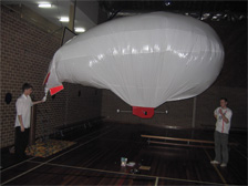
Filling
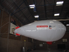
Flying
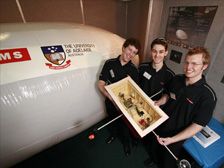
The team