GKN Aerospace utilizes robot cell from Nikon Metrology for its research

Photo by Nikon Metrology
Nikon Metrology Tamworth (UK) has recently delivered a robot cell for GKN Aerospace’s research center on the Isle of Wight, as part of UK Government STEM project. This technology demonstrator has at its heart an optical metrology system, guiding the robotic processes and managing the build, a process called “Metrology Assisted Production”.
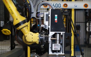
The goal of the project was to “one-shot” drill and countersink – then apply adhesive and fastener. The first major technology advance was to prove that a robot can take one tool (drill and countersink) and make the hole (up to 8mm diameter), then pick-up another separate tool (fastener) and go to exactly the same place/vector to apply the fastener. This meant a multi-function end effector wasn’t needed – which in-turn meant only a small payload robot is needed, on a small width rail. This dramatically reduces the capital investment in the robot solution, and requires much less energy, so it’s a greener solution as well. The technology to guide the robot to this precision is called “Adaptive Robot Control.”
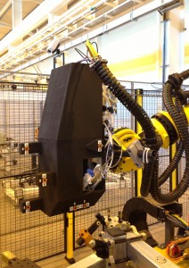
Nikon Metrology designed and built the applied end effectors. The drill uses a high speed/low torque spindle. This was an evolution of a system used with partners Wright Industries on another GKN project in the USA. The advantage of this system is that no pressure foot is required to clamp-up the drill to the surface, again simplifying the drill which only weighs 25Kg. The blind-sided fastener tool with integrated adhesive injector was even lighter (20Kg).
The fasteners chosen for the project were supplied by Monogram, and Nikon Metrology built their installation unit inside the robot process tool.Both tools included automatic tool changers and full instrumentation for metrology guidance. A force feedback system was also foreseen , but remained unused – Adaptive Control being more than sufficient to get both tools, separately, to the exact same target.

Photo by Nikon Metrology
Within the working volume of the optical metrology system, the robot also used a third tool for inspection and control purposes. This is a Nikon Metrology integrated laser line scanner (MMDx50). The first task in the cell is for the robot to scan the upper surface of the composite aerospace part. This is to verify the true surface is within build tolerances (inspection) and to offset automatically all of the targets created off-line in Delmia onto the true surface. One reason being: to manage the countersink height whilst keeping the drill tool simple (a countersink is an enlarged top part of a hole so that the head of a fastener will lie flush with or below the surface). After drilling/countersinking, the robot held laser scanner is used to inspect the holes and countersinks, before the fastening. After the fastening the laser scanner is used again to check fastener flushness.
So the component enters the cell unprocessed, and leaves completed and inspected. As a side benefit, a simple support was put onto one of the robot tools, and used as a reference to set jig clamping points. So the robot was programmed to go to the nominal tooling positions, and then corrected to remove robot inaccuracies using Adaptive Robot Control. The support was used to set the Delfoi flexible tooling system “top-down” which was a significant improvement in time, and accuracy, compared to previous baseline solution of using a laser tracker where the jig is built “bottom-up”.
The project partners that contributed to this successful installation were beside the technical team from GKN; Fanuc Robotics who supplied the robot and rail, AMRC who managed the manual assembly (pre-robot cell) and Delfoi who supplied and designed the flexible tooling and provided support to use Delmia software.
For more information, please visit www.nikonmetrology.com.
Watch this video to learn more about how the D-flex can be positioned independent from base and fixture inaccuracies!
News Categories
- » NEWS HOME
- » Automation & Robotics
- » Industry 4.0
- » Material Handling
- » Sensors
- » Quality & Testing
- » Machine Vision
- » Laser & Optics
- » Metalworking
- » Motion Control & Drives
- » Hydraulics & Pneumatics
- » Process Industry
- » Renewable Energy
- » Agriculture
- » Home & Office Furniture
- » Environmental Tech


