SensoPart’s VISOR® series of vision sensors now offer new calibration functions
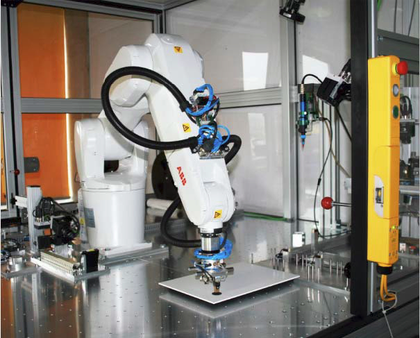
VISOR® with calibration plate or robot
Photo by SensoPart Industriesensorik GmbH
Sensor manufacturer SensoPart Industriesensorik extends the functional scope of its VISOR® series of vision sensors to include new, comfortable calibration functions: positions and distances in the sensor image can now be easily converted into relative world coordinates or absolute robot coordinates. Distortions resulting from diagonal view angles and other image errors are simultaneously corrected. These new functions are now immediately available in a free software upgrade.
1. Conversion of image pixels into metric world coordinates:
When checking or measuring components, it is often preferable to have position and distance values in real world units, such as millimetres, and not just in image pixels. Values can now be converted in just a mouse click, with the aid of a special calibration plate and an appropriate function in the VISOR® configuration program. Relative world coordinates are then indicated, as, for example, often required for part measurement.
The VISOR® simultaneously also corrects any image errors when converting values into world coordinates. These include perspective distortions which are caused by the diagonal object detection angle used in many applications. Lens distortions resulting from a short focal width are also corrected. If the object to be detected is not on the same plane as the calibration plate, a height offset can also be taken into consideration. This guarantees precisely-calculated, metric distance values.
2. Output of part position in absolute robot coordinates:
The VISOR® software upgrade also offers comfortable new functions for robot control. The conversion of object/image coordinates into absolute robot coordinates no longer requires laborious programming in the robot control or PLC systems, but is performed directly in the sensor through one-time calibration. This represents a considerable saving in both time and effort for users and integrators, as well as a significant boost in efficiency.
Coordinate conversion requires the one-time creation of a so-called point pair list in the VISOR® operating software. This is done by moving the robot to different positions, where appropriate image and real world coordinates are then recorded in the VISOR® configuration program. The robot base or tool centre point can, for example, be used as an absolute reference point. Data input is carried out either manually (in which image coordinates are comfortably recorded with a “snap” function) or fully-automatically through interface commands from the robot control system (e.g. for recalibration after modification).
It is also possible to enter a height offset value if necessary, as with calibration using the calibration plate. The additional “Grip point correction” function can be used to modify an automatically determined centre point and take a different grip position into account, e.g. handle at the side of an object. If a part is to be gripped on its outer contours, a further function can be used to check the available space around the part. These options – which are unique in vision sensors – enable simple and comfortable configuration of pick & place applications.
Image and lens distortions are also simultaneously corrected during conversion into robot coordinates, so that the vision sensor supplies highly-accurate, metric position values at all times.
For more information, please visit http://www.sensopart.com.
News Categories
- » NEWS HOME
- » Automation & Robotics
- » Industry 4.0
- » Material Handling
- » Sensors
- » Quality & Testing
- » Machine Vision
- » Laser & Optics
- » Metalworking
- » Motion Control & Drives
- » Hydraulics & Pneumatics
- » Process Industry
- » Renewable Energy
- » Agriculture
- » Home & Office Furniture
- » Environmental Tech


Tags
|
|
|
|
|
|
|
|
|
|
|
|
|
|
|
|
|
|