Flow Rate
max. 12.000 m³/h
Delivery Head
max. 12 m L.C.
Temperature Range
-120 °C to +250 °C
Pressure Rating
max. PN 100
key facts
-
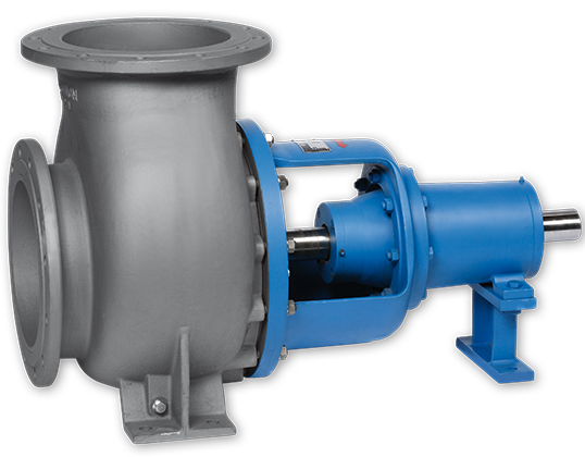
Horizontally Mounted Propeller Pump
-
Pipe-Bend Casing made of Welded Cast Steel
-
Adjustable Propeller Blades screwed to the Hub
-
Shaft Seal: Face Seal or Gland Packing
-
Propeller can reverse Direction

DESIGN
- Horizontally Mounted Propeller Pump
- Pipe-Bend Casing made of welded Cast Steel
- Adjustable Propeller Blades screwed to the Hub
- Shaft Seal: Face Seal or Gland Packing
- Propeller can reverse Direction
OPERATING RANGE
| Flow Rate | Q | 12.000 m³/h |
| Delivery Head | H | max. 12 m L.C. |
| Temperature Range | t | -120 °C to +250 °C |
| Pressure Rating | p | max. PN 100 |
Special constructions and higher outputs available
TYPICAL APPLICATION
- Acids
- Lyes
- Paper and Cellulose Mash
- Brine (Evaporation Plants)
- Mineral Fertilisers (Liquid)
- Sea Water
- Cooling Water
- Dyes
Special configurations
- PV: Propeller Blades can be adjusted steplessly while the Pump is running
- PK: The Propeller Unit can be completely dismantled with the Casing intact
- Flow Direction can be reversed by repositioning the Propeller Blades
CUSTOM MATERIALS
| Components | A-8 | S-8 |
| Casing | 316 Austenite | Stahlguss |
| Impeller | 316 Austenite | 316 Austenite |
| Containment Shell | Hastelloy C | Hastelloy C |
| Pump Shaft | 316 Austenite | 316 Austenite / C-Steel |
| Bearing Lantern / Bearing Carrier | Stahlguss | Stahlguss |
| Drive Shaft | C-Steel | C-Steel |
Further Materials upon Request
DESIGN VARIANTS
The pumps are outfitted with a heat jacket and pump casing (H1) and/or a heat jacket in the bearing lantern (H2). Both heat jackets can be realized either separately or in conjunction with a bypass line. The heat jackets in the standard construction are rated for operating pressure of 16 bar at 200 °C (steam) or 6 bar at 350 °C. The heat jackets can also be used for cooling.
When solids-containing liquids are being transported, the internal filter prevents inadmissibly large particles from entering the flow channels, and from there the magnetic coupling and internal bearings.
These external connections allow for external flushing, feeding and/or venting. Connection E1 is used in situations where a continuous feed into the magnet drive is desired. Connection E2 is used suitable for short-term flushing, or for external venting of the magnetic coupling.
The double isolation shell should be used in situations requiring a high level of safety. The unit consists of two interlocking isolation shells, both of which are rated for the relevant operating conditions. If one of the two units is damaged, the casing still remains leaktight. The gap between the two units can be monitored.
Inducers are often used in cases where the installation’s NPSH values are extremely low. Inducers substantially reduce pump NPSH throughout the installation without altering pump characteristics. Inducer J can be retrofitted on existing pumps, in most cases with only a minimum amount of pump modification.


