

Flow Rate
max. 300 m³/h
Delivery Head
max. 2.200 m L.C.
Temperature Range
-120 °C to +350 °C
Pressure Rating
max. PN 250
key facts
-
Design according to DIN EN ISO 15783
-
Maintenance-Free Permanent Magnet Drive
-
Modular Design
-
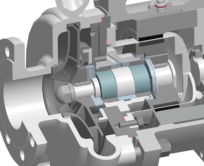
No Dynamic Seal, Separation of Liquid Chamber and Atmosphere by Means of Containment Shell
-
Barrel Design Version without Variable Seal
-
Impeller Arrangement in Series; max. 15 Stages
-
First Low-NPSH Stage for Improved Suction Performance


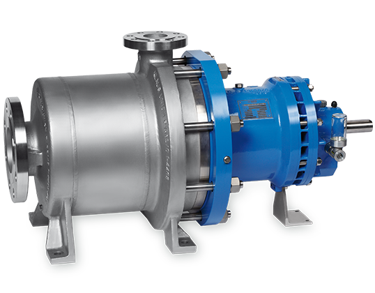
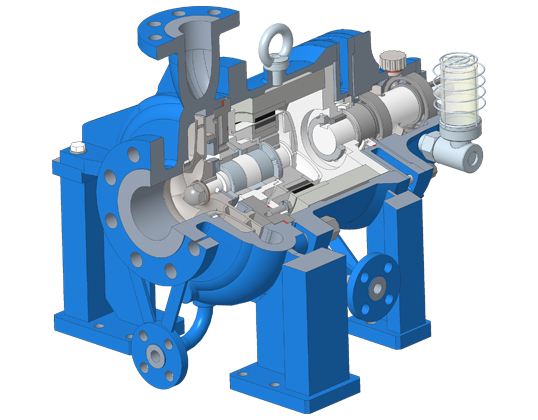
- Multi-Stage Centrifugal Pump in Process Design
- Barrel Design Housing with just Two Baskets
- Impeller Arrangement in Series; max. 15 Stages
- First Low-NPSH Stage for Improved Suction Performance
- Synchronous Permanent Magnet Drive
- Easy to Maintain
- Seperation of Liquid Chamber and Atmosphere by Means of Isolation Shell
- Centerline Support
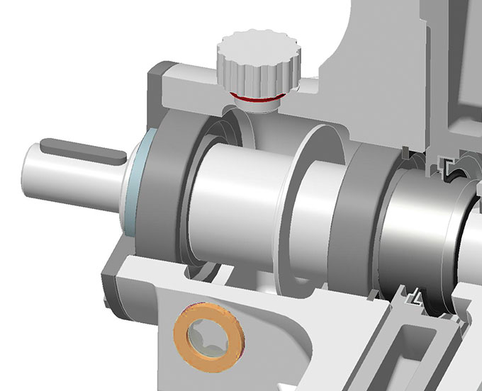
- Bearing Bracket with Oil-Lubricated or Greased-for-Life Anti-Friction Bearings; Optional: Close-Coupled Design
- Product-Lubricated Journal Bearings; Made of Silicon Carbide (SSiC); Customized Materials (e.g. Carbon, WOC etc.) on demand
| Flow Rate | Q | 300 m³/h |
| Delivery Head | H | max. 2.200 m L.C. |
| Temperature Range | t | -120 °C to +350 °C |
| Pressure Rating | p | max. PN 250 |
- Acids
- Lyes
- Hydrocarbons
- Hot Water
- Heat Transfer Liquids
- Liquid Gases
- Aggressive, Explosive, Toxic an Malodorous Liquids
- Pump casing: 1.4408 or 1.0619
- Impeller: 1.4408
- Containment shell: 1.4571/2.4610
- Magnet carrier: 1.4571
- Radial journal bearings: Silicon Carbide
- Intermediate lantern: 1.0619
- Bearing carrier: 0.7043
- Further materials upon request.
Flow Rate
max. 360 m³/h
Delivery Head
max. 580 m
Temperature Range
-40 °C to +250 °C
Pressure Rating
max. PN 63
KEY FACTS
-
Design according to DIN EN ISO 15783
-
Maintenance-Free Permanent Magnet Drive
-
Modular Design
-
No Dynamic Seal, Separation of Liquid Chamber and Atmosphere by Means of Containment Shell
-
Tension Rod Version with Variable Seal
-
Impeller Arrangement in Series; max. 6 Stages
-
First Low-NPSH Stage for Improved Suction Performance
- Multi-Stage Centrifugal Pump in Process Design
- Tension Rod Design with Variable Seal
- Impeller Arrangement in Series; max. 6 Stages
- First Low-NPSH Stage for Improved Suction Performance
- Synchronous Permanent Magnet Drive
- Easy to Maintain
- Seperation of Liquid Chamber and Atmosphere by Means of Isolation Shell
- Centerline Support
- Bearing Bracket with Oil-Lubricated or Greased-for-Life Anti-Friction Bearings; Optional: Close-Coupled Design
- Product-Lubricated Journal Bearings; Made of Silicon Carbide (SSiC); Customized Materials (e.g. Carbon, WOC etc.) on demand
| Flow Rate | Q | 350 m³/h |
| Delivery Head | H | max. 700 m |
| Temperature Range | t | -120 °C to +350 °C |
| Pressure Rating | p | max. PN 200 |
- Acids
- Lyes
- Hydrocarbons
- Hot Water
- Heat Transfer Liquids
- Liquid Gases
- Aggressive, Explosive and Toxic Liquids
- Pump casing: 1.4408 or 1.0619
- Impeller: 1.4408
- Containment shell: 1.4571/2.4610
- Magnet carrier: 1.4571
- Radial journal bearings: Silicon Carbide
- Intermediate lantern: 1.0619
- Bearing carrier: 0.7043
- Further materials upon request
Flow Rate
max. 540 m³/h
Delivery Head
max. 1.300 m
Temperature Range
-40 °C to +180 °C
Pressure Rating
max. PN 100
KEY FACTS
-
Design according to DIN EN ISO 15783
-
Maintenance-Free Permanent Magnet Drive
-
Modular Design
-
No Dynamic Seal, Separation of Liquid Chamber and Atmosphere by Means of Containment Shell
-
Impellers in Pairs or back-to-back; max. 6 Stages
-
First Low-NPSH Stage for Improved Suction Performance
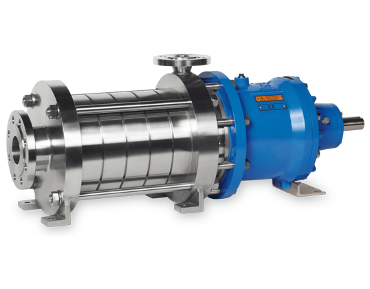
- Multi-Stage Centrifugal Pump in Process Design
- Impeller Arrangement in Pairs or back-to-back
- Max. 6 Stages
- First Low-NPSH Stage for Improved Suction Performance
- Synchronous Permanent Magnet Drive
- Easy to Maintain
- Seperation of Liquid Chamber and Atmosphere by Means of Isolation Shell
- Centerline Support
- Bearing Bracket with Oil-Lubricated or Greased-for-Life Anti-Friction Bearings; Optional: Close-Coupled Design
- Product-Lubricated Journal Bearings; Made of Silicon Carbide (SSiC); Customized Materials (e.g. Carbon, WOC etc.) on demand
| Flow Rate | Q | 540 m³/h |
| Delivery Head | H | max. 1.300 m |
| Temperature Range | t | -40 °C to +180 °C |
| Pressure Rating | p | max. PN 100 |
- Acids
- Lyes
- Hydrocarbons
- Hot Water
- Heat Transfer Liquids
- Liquid Gases
- Aggressive, Explosive and Toxic Liquids
- Pump casing: 1.4408 or 1.0619
- Impeller: 1.4408
- Containment shell: 1.4571/2.4610
- Magnet carrier: 1.4571
- Radial journal bearings: Silicon Carbide
- Intermediate lantern: 1.0619
- Bearing carrier: 0.7043
- Further materials upon request
Flow Rate
max. 350 m³/h
Delivery Head
max. 700 m
Temperature Range
-120 °C to +300 °C
Pressure Rating
max. PN 200
key facts
- No Alignment between Pump and Motor
- No Coupling and Coupling Guard
- No Ball Bearings
- Pump does not require scheduled Maintenance
- No Oil Lubrication necessary
- Lower noise level
- High Stiffness of the Pump Shaft because of small overhung compared to Pumps with Shaft Seals
- Use of standard high efficient IEC and NEMA Motors contrary to canned Motors
- Better availability with standard Motors
- Maintenance of Motors is standardized and can be done by the customer on site
- Base Plates for Close-Coupled Design do not need to be rigid acc. to API 685 – 7.3
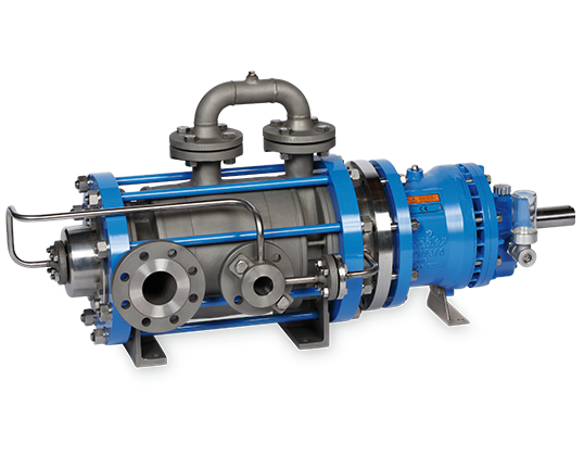
- Process oriented design
- Barrel design model (no variable seal)
- only 2 static seals
- 2-6 stages
- Magnet drive
- Leakproof
- Horizontally mounted
- Modular System
- Jacketed bearing lantern
- Barrel casing heated
- Heating connection
- Oiled ball bearing
- Thermal barrier
- Secondary seal
| Flow Rate | Q | 350 m³/h |
| Delivery Head | H | max. 700 m |
| Temperature Range | t | -120 °C bis +300 °C |
| Pressure Rating | p | max. PN 200 |
- Acids
- Lyes
- Hydrocarbons
- Hot Water
- Heat Transfer Liquids
- Liquid Gases
- Aggressive, Explosive and Toxic Liquids
- Pump casing: 1.4408 oder 1.0619
- Impeller: 1.4408
- Containment shell: 1.4571/2.4610
- Magnet carrier: 1.4571
- Journal bearings: Siliciumcarbid
- Intermediate lantern 1.0619
- Bearing carrier 0.7043
- Other materials available
NACHSETZZEICHEN (AUSFÜHRUNGEN):
| H1 | heated pump casing |
| H2 | jacketed bearing lantern |
| S | thermal barrier without secondary seal |
| W | thermal barrier with secondary seal |
| F | internal filter |
| E1 | external feeding, internal secondary-flow boring non-enclosed |
| E2 | external flushing and vening; internal secondary-flow non-enclosed |
| E1F | external secondary flow with main flow filter per DGRL |
| J | inducer |
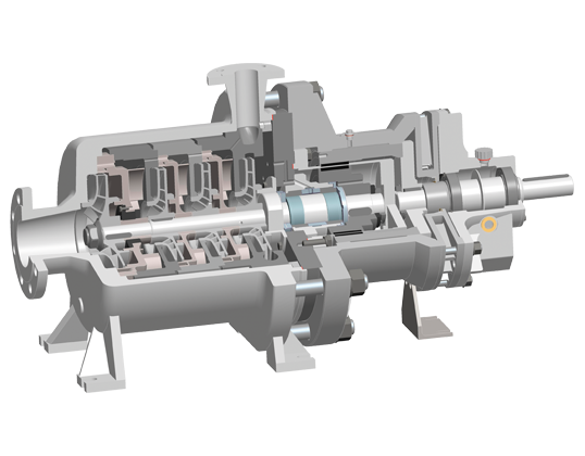
DESIGN VARIANTS
The pumps are outfitted with a heat jacket and pump casing (H1) and/or a heat jacket in the bearing lantern (H2). Both heat jackets can be realized either separately or in conjunction with a bypass line. The heat jackets in the standard construction are rated for operating pressure of 16 bar at 200 °C (steam) or 6 bar at 350 °C. The heat jackets can also be used for cooling.
When solids-containing liquids are being transported, the internal filter prevents inadmissibly large particles from entering the flow channels, and from there the magnetic coupling and internal bearings.
These external connections allow for external flushing, feeding and/or venting. Connection E1 is used in situations where a continuous feed into the magnet drive is desired. Connection E2 is used suitable for short-term flushing, or for external venting of the magnetic coupling.
The double isolation shell should be used in situations requiring a high level of safety. The unit consists of two interlocking isolation shells, both of which are rated for the relevant operating conditions. If one of the two units is damaged, the casing still remains leaktight. The gap between the two units can be monitored.
Inducers are often used in cases where the installation’s NPSH values are extremely low. Inducers substantially reduce pump NPSH throughout the installation without altering pump characteristics. Inducer J can be retrofitted on existing pumps, in most cases with only a minimum amount of pump modification.