
TCSPC and Time Tagging Electronics
HydraHarp 400 25 % off
Multichannel Picosecond Event Timer & TCSPC Module
- Anniversary offer: 25% off on HydraHarp 400
- Ships within 2 weeks
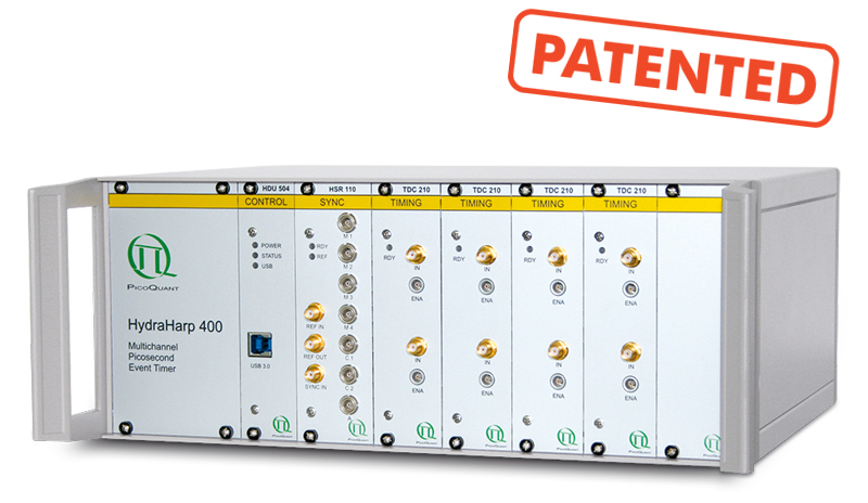
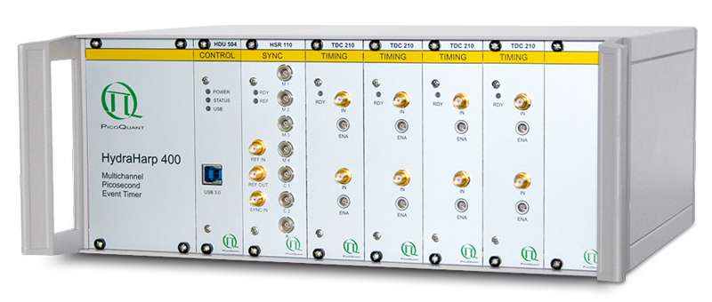
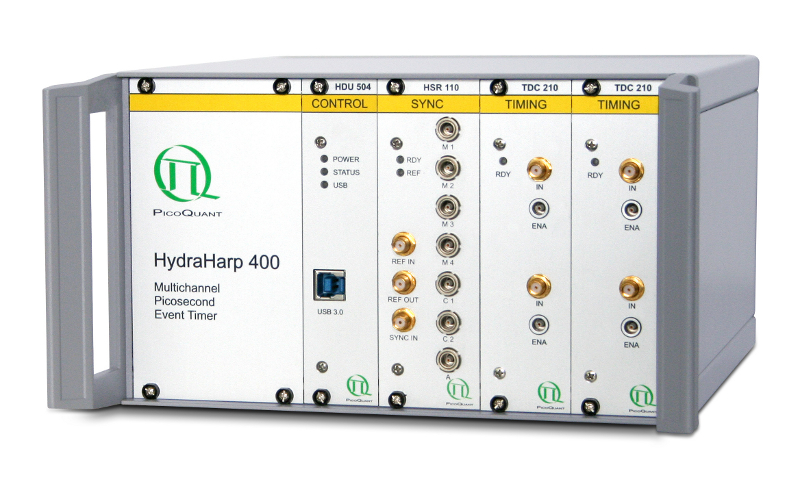
- Compact box with USB 3.0 connection and modular, scalable design (patented)
- Up to 8 independent input channels and common sync channel (trigger rate up to 150 MHz)
- 65536 histogram bins per channel, minimum width 1 ps
- Time tagging with sustained count rates up to 40 Mcps
- Histogrammer measurement ranges from 65 ns to 2.19 s
- Count rate up to 12.5 million counts/sec per channel
- Adjustable input delay for each channel with 1 ps resolution
- Multi-stop capability for efficiency at slow repetition rates
- External synchronization signals for (fluorescence lifetime) imaging or other control events
- External reference clock input and output
- NEW: With drivers and Python wrapper snAPI for seamless communication, configuration, data handling and custom programming
 Get in touch

 The HydraHarp 400 is a high-end, easy to use, plug and play Time Interval Analyzer (TIA) and Time-Correlated Single Photon Counting (TCSPC) system with scalability for multiple channels (covered by patent DE 10 2008 004 549). It is connected to a PC through a USB 3.0 high speed interface. The high quality and reliability of the HydraHarp 400 is expressed by a unique 5-year limited warranty.
Multiple input channels for highly flexible use
") The HydraHarp 400 is available in different sizes that permit to install up to 4 or up to 8 identical synchronized but independent input channels. They can be used as detector inputs for coincidence correlation experiments or as independent stop inputs for TCSPC. A dedicated common sync input is provided for TCSPC with fast excitation sources. This allows forward start-stop operation at the full repetition rate of mode locked lasers with stable repetition rate up to 150 MHz. Experiments with low repetition rate benefit from the HydraHarp's multi-stop capability.
The HydraHarp 400 is available in different sizes that permit to install up to 4 or up to 8 identical synchronized but independent input channels. They can be used as detector inputs for coincidence correlation experiments or as independent stop inputs for TCSPC. A dedicated common sync input is provided for TCSPC with fast excitation sources. This allows forward start-stop operation at the full repetition rate of mode locked lasers with stable repetition rate up to 150 MHz. Experiments with low repetition rate benefit from the HydraHarp's multi-stop capability.
Independent channels, 1 ps resolution
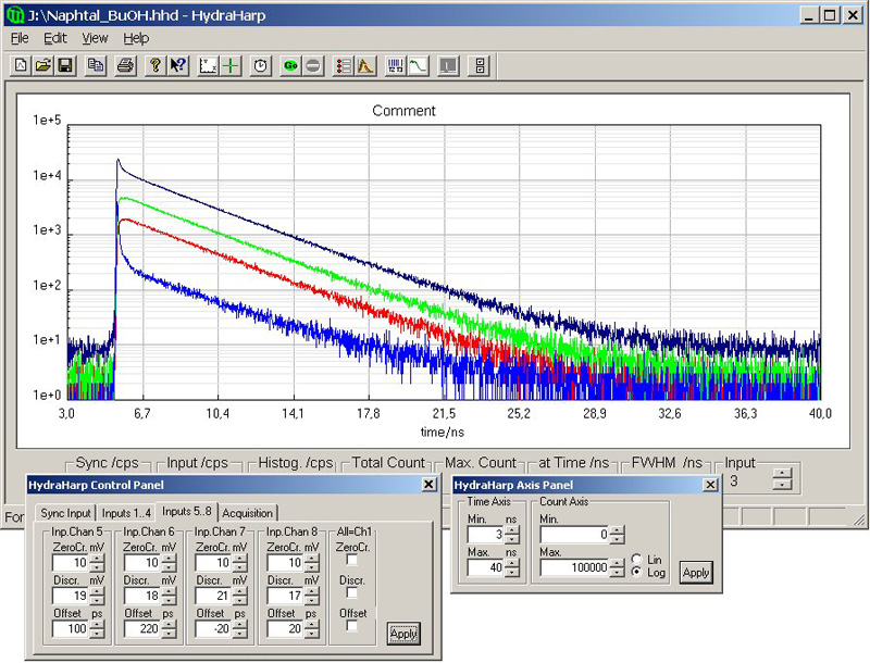
The design of the HydraHarp 400 allows high measurement rates up to 12.5 million counts/sec per channel and provides a highly stable, crystal calibrated time resolution of 1 ps. Along with the extremely low differential non-linearity of the instrument, excellent data quality can be obtained. As a special feature, an external time base can be used to synchronize the internal clock in relation to other timing devices. The instrument's timing resolution is well matched to even the fastest detectors currently available: the SPAD detectors of the PDM series or micro-channel plate Photomultiplier Tubes (MCP). All input channels are equipped with Constant Fraction Discriminators (CFD), sensitive on the falling edge.
Adjustable delay in each input channel
 The HydraHarp 400 offers 65536 histogram bins per input channel and allows to collect more than 4 billion counts (32 bits) per bin. Each input channel even has an internal adjustable delay with ±100 ns range at 1 ps resolution. This unique feature eliminates the need for specially adapted cable lengths or cable delays for different experimental set-ups.
Operation as time tagger
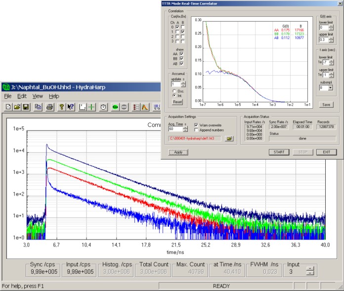
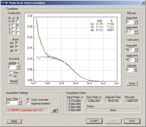
A time-tagged mode for recording of individual photon events with their arrival time on all channels allows the most sophisticated offline analysis of the photon dynamics. Time-Tagged Time-Resolved (TTTR) data can also be correlated in real-time for monitoring of FCS experiments at count rates up to 1,000,000 counts/sec. In TTTR mode, the device can be synchronized with other hardware such as scanners.
| Input Channels and Sync | |
|---|---|
| Discrimination | Constant Fraction Discriminator (CFD) included in all channels, software adjustable |
| Input voltage range | 0 mV to -1000 mV, optimum: -100 mV to -500 mV |
| Trigger point | falling edge |
| Trigger pulse width | 0.5 ns to 30 ns |
| Trigger pulse rise/fall time | 2 ns max. |
| External Reference Clock | |
| Input | 10 MHz, min. 200 mV, max. 1 V pp, 50 Ohms, AC coupled |
| Output | 10 MHz, 300 mV pp, 50 Ohms, AC coupled |
| Time to Digital Converters | |
| Minimum time bin width | 1 ps |
| Timing precision* | < 12 ps rms |
| Timing precision / √2* | < 8.5 ps rms |
| Full scale range - histogram mode | 65 ns to 2.19 s (depending on chosen resolution: 1, 2, 4, ..., 33 554 432 ps) |
| Full scale range - time-tagged mode | infinite |
| Maximum count rate per input channel | 12.5 × 10⁶ counts/sec |
| Maximum sync rate | 150 MHz |
| Adjustable delay range for each input channel | ± 100 ns, resolution 1 ps |
| Dead time | < 80 ns |
| Differential non-linearity | < 2 % peak, < 0.2 % rms (over full measurement range) |
| Histogrammer | |
| Count depth per time bin | 4.294.967.296 (32 bit) |
| Maximum number of time bins | 65536 |
| Acquisition time | 1 ms to 100 hours |
| TTTR Engine | |
| T2 mode resolution | 1 ps |
| T3 mode resolution | 1, 2, 4, ..., 33 554 432 ps |
| FiFo buffer depth (records) | 2097152 |
| Sustained throughput** (sum of all channels) |
typ. 40 × 106 events/sec |
| Operation | |
| PC interface | USB 3.0 |
| PC requirements | min. 1 GHz CPU clock, min. 1 GB memory |
| Operating system | Windows 10/11 |
| Power consumption | small mainframe < 50 W, large mainframe < 100 W at 100 to 240 VAC |
* In order to determine the timing precision it is necessary to repeatedly measure a time difference and to calculate the standard deviation (rms error) of these measurements. This is done by splitting an electrical signal from a pulse generator and feeding the two signals each to a separate input channel. The differences of the measured pulse arrival times are calculated along with the corresponding standard deviation. This latter value is the rms jitter which we use to specify the timing precision. However, calculating such a time difference requires two time measurements. Therefore, following from error propagation laws, the single channel rms error is obtained by dividing the previously calculated standard deviation by √2. We also specify this single channel rms error here for comparison with other products.
** Sustained throughput depends on configuration and performance of host PC.
All Information given here is reliable to our best knowledge. However, no responsibility is assumed for possible inaccuracies or omissions. Specifications and external appearances are subject to change without notice.
 The HydraHarp software provides functions such as the setting of measurement parameters, display of results, loading and saving of measurement parameters and measurement curves. Important measurement characteristics such as count rate, count maximum, position and peak width are displayed continuously. A comprehensive online help function shortens the users' learning curve. A library for custom programming, e.g., with LabVIEW is also available, both for Windows and Linux.
Measurement data from the HydraHarp 400 can be analyzed by different software packages. For multi-exponential reconvolution the EasyTau 2 software is an ideal tool. For the analysis of TTTR data (e.g., FLIM, FCS, FLCS, FRET, BIFL, etc.) the SymPhoTime 64 software suite is the tool of choice. Analysis of photon correlations is best performed with the QuCoa software package.
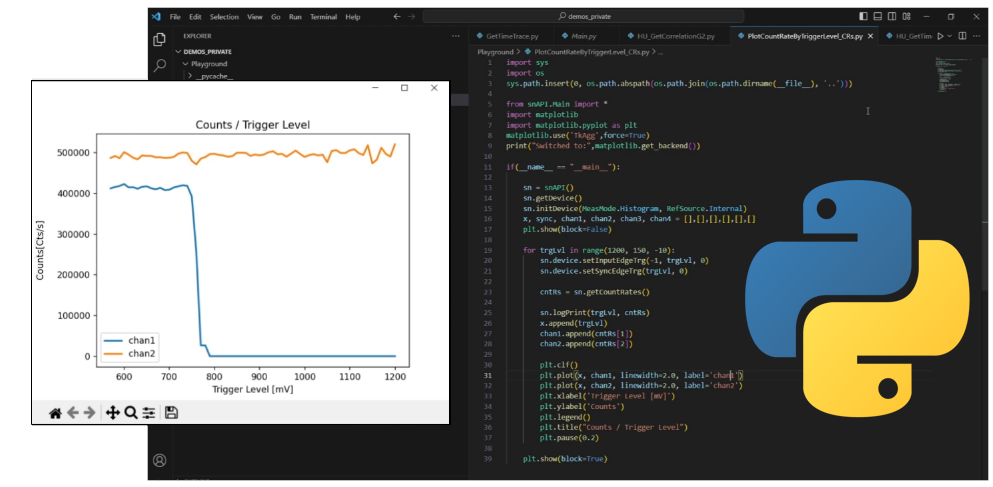
 Fast, intuitive, and versatile Python wrapper snAPI NEW
snAPI serves as a bridge between the capabilities of PicoQuant's TCSPC devices and the Python ecosystem, offering efficient device communication, configuration, and data handling for all users.
Operation and software features (current version: 3.0.0.4)
The HydraHarp 400 can be used in various operation modes.
Integration mode
Measurement of the accumulated events as a function of time, manually started, stopped manually or upon overflow or expiration of a chosen collection time or upon reaching of a defined number of counts. 512 curves with up to 65536 time channels, more than 4 billion counts per time channel (32 bits).
Oscilloscope mode
Repetitive measurement and on-line display, very useful for optical alignment. Flicker free histogram display updates and large rate meters for work in the distance.
Time-Resolved Emission Spectra (TRES)
An optional hardware and software add-on allows to control a monochromator from within the HydraHarp software, allowing automated measurement of Time-Resolved Emission Spectra. This mode drives a monochromator via a stepper motor for collection of spectrally resolved lifetime histograms. Data is collected as in standard Integration Mode and saved in different blocks of memory for each wavelength. Four different monochromator types are currently supported: Sciencetech 9030, Sciencetech 9055, Acton Research SP-2155 and Acton Research SP-275.
Time-Tagged Time-Resolved mode(s) (TTTR)
Continuously recording events without onboard histogramming straight to disk. Together with the channel number the arrival time of each event with respect to the beginning of the experiment is recorded for ultimate flexibility in offline data analysis, e.g., in single molecule detection and Burst Integrated Fluorescence Lifetime (BIFL) measurement as well as time-resolved FCS, coincidence correlation (antibunching, etc.) or time-interval analysis. A real-time correlator is included in the TTTR mode which can be extremely useful in setting up and monitoring of FCS experiments. Fast transfer and a large FIFO buffer allow huge count rates without any loss of data. Up to four different external synchronization signals ("markers") can be fed into the data stream and allow to synchronize the data acquisition with external hardware such as scanners for Fluorescence Lifetime Imaging (FLIM).
Software overview
The HydraHarp 400 software allows the control of all measurement parameters provided by the HydraHarp 400 module. The input channels are programmable for a variety of signal types. All functions of the system are controlled by a software interface for Windows 10 and 11. The software provides functions such as the setting of measurement parameters, display of measurement results, loading and saving of measurement parameters and measurement curves. Important measurement characteristics such as count rate, count maximum and position, and histogram width (FWHM) are displayed continuously. A comprehensive online help function shortens the user's learning curve. Software upgrades for extended functionality will be available with further product development.
 A library (DLL) for custom program development is also provided and allows to build your own applications, e.g., in LabVIEW , C++, Delphi, Python or Matlab. Demo code is provided for an easy start. A Windows as well as a Linux version is available. The libraries are API compatible, so that applications can easily be ported between the platforms.

Current software and developer's library version: 3.0.0.4
The new software version features includes bug fixes and more advanced demos in C, C#, Python and Delphi, including some new demos for instant processing of TTTR data.
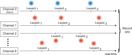
Time-Tagged Time-Resolved (TTTR) mode allows the recording of individual count events directly to hard disk or computer memory. The timing of each photon is captured as an event record without any early data reduction (such as on-board forming of histograms). This mode is particularly interesting where, e.g., the dynamics in a fluorescence process are to be investigated in depth. The availability of the full timing information permits photon burst identification, which is of great value, e.g., for single molecule spectroscopy in a liquid flow. Other typical applications are Fluorescence Correlation Spectroscopy (FCS) and Burst Integrated Fluorescence Lifetime (BIFL) measurements. Together with an appropriate scan controller, TTTR mode is also suitable for ultra fast Fluorescence Lifetime Imaging (FLIM) with unlimited image size. Applications beyond fluorescence spectroscopy are, e.g., time interval analysis, quantum optics and related basic rearch. The HydraHarp 400 actually supports two different time-tagging modes, T2 and T3 Mode - a concept originally introduced with the PicoHarp 300. They differ slightly in their use of the input channels and by using the suitable mode, a very wide range of applications can be covered.
T2 mode
In T2 Mode all signal inputs of the HydraHarp 400 are functionally identical. There is no dedication of one channel to a sync signal. All inputs can be used to connect photon detectors. The events from all channels are recorded independently and treated equally. In each case an event record is generated that contains information about the channel it came from and the arrival time of the event with respect to the overall measurement start. If the time tag overflows, a special overflow marker record is inserted in the data stream, so that upon processing of the data stream a theoretically infinite time span can be recovered at full resolution. Dead times exist only within each channel (80 ns typ.) but not across the channels. Therefore, cross correlations can be calculated down to zero lag time. This allows powerful new applications such as FCS with lag times from picoseconds to hours to be implemented with one instrument. Autocorrelations can also be calculated at the full resolution but of course only starting from lag times larger than the deadtime.

T3 mode
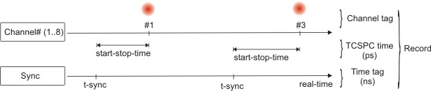
The T3 Mode is specifically designed to use periodic sync signals from pulsed lasers with high repetition rate up to 150 MHz. This signal is connected to the dedicated sync channel. As far as the experimental setup is concerned, this is similar to classic TCSPC in histogramming mode. In addition to the picosecond start-stop timing, the channel number is recorded and each event is time tagged with respect to the beginning of the experiment. The time tag is obtained by simply counting sync pulses. From the T3 Mode event records it is therefore possible to precisely determine which sync period a photon event belongs to. Since the sync period is also known precisely, this furthermore allows to reconstruct the arrival time of the photon with respect to the overall experiment time. If the counter overflows, a special overflow marker record is inserted in the data stream, so that upon processing of the data stream a theoretically infinite time span can be recovered.

External event markers
Both TTTR modes support capturing up to four external marker events that can be fed to the instrument as TTL signals via the front panel. These events are recorded as part of the TTTR data stream. This allows to precisely synchronize the TTTR measurement with almost any experiment. The most important applications of this feature are FLIM and FRET imaging. This concept is used in the cutting-edge time-resolved confocal microscope MicroTime 200.
Software support
The acquisition software provided with the instrument comes with a rich set of demo programs that enable users to write their own analysis and display programs for TTTR data. Users who prefer to use standard data analysis algorithms out of the box may want to consider the powerful SymPhoTime 64 software suite. It implements a wide range of state-of-the-art analysis algorithms for FLIM, FCS and FRET to name only a few. Analysis of photon correlations for e.g. coincidence correlation or coincidence counting is best performed with the QuCoa software package.
The HydraHarp 400 can be used for various applications that can make use of a multi-channel TCSPC and/or time tagging system with independent channels, such as:
- Time-Resolved Fluorescence
- Fluorescence Lifetime Imaging (FLIM)
- Phosphorescence Lifetime Imaging (PLIM)
- Fluorescence Correlation Spectroscopy (FCS)
- Fluorescence Lifetime Correlation Spectroscopy (FLCS)
- Foerster Resonance Energy Transfer (FRET)
- Stimulated Emission Depletion Microscopy (STED)
- Dual Focus Fluorescence Correlation Spectroscopy (2fFCS)
- Pulsed Interleaved Excitation (PIE)
- Fluorescence Anisotropy (Polarization)
- Single Molecule Spectroscopy / Detection
- Singlet Oxygen
- Time-Resolved Photoluminescence (TRPL)
- TRPL Imaging
- Lanthanide Upconversion
- Bunch Purity
- LIDAR/Ranging/SLR
- Antibunching
- Diffuse Optical Tomography and Imaging
- Coincidence Correlation
- Quantum Communication
- Quantum Entanglement
- Quantum Teleportation
- Quantum Information Processing
- Positron Annihilation Lifetime Spectroscopy (PALS)
- Time response characterization of optoelectronic devices
- Intensity interferometry
- Time Interval Analysis (TIA)
- Thomas-Bollinger single photon method
The following documents are available for download:
- Datasheet HydraHarp 400
- Brochure about PicoQuant's photon counting and timing products
- Technical note: Time-Correlated Single Photon Counting (TCSPC)
Latest 10 publications referencing HydraHarp 400
The following list is an extract of 10 recent publications from our bibliography that either bear reference or are releated to this product in some way. Do you miss your publication? If yes, we will be happy to include it in our bibliography. Please send an e-mail to info@picoquant.com containing the appropriate citation. Thank you very much in advance for your kind co-operation.