
- Offer Profile
- ABB offers an extensive range of innovative products and solutions for machine safety systems. We have great experience of practical application of safety requirements and standards from both authorities and production. We are represented in standardization organisations for machine safety and we work daily with the practical application of safety requirements in combination with production requirements. We offer a complete range of safety products, designed to make your machine safety system easy to build. We develop these innovative products continuously, in cooperation with our customers.
Safety products
- ABB offers an extensive range of innovative products and solutions for machine safety systems.
Experience
We have great experience of practical application of safety requirements and standards from both authorities and production. We are represented in standardization organisations for machine safety and we work daily with the practical application of safety requirements in combination with production requirements.
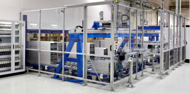
Systems
We deliver everything from a single safety solution to complete safety systems for single machines or entire production lines.
Products
We offer a complete range of safety products, designed to make your machine safety system easy to build. We develop these innovative products continuously, in cooperation with our customers. 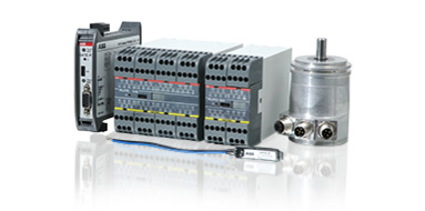
Programmable safety controllers
- Pluto safety-PLC system for supervision of machine safety applications.
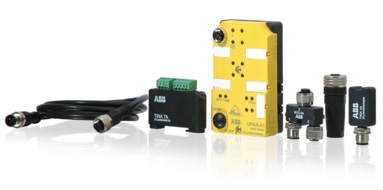
Safety controllers
- Vital safety module for control of smaller machine safety systems and safety relays for all kinds of safety devices.
Fencing systems
- Stable and flexible fencing system and roller doors.

Safety sensors, switches and locks
- Non-contact sensors, key switches and locks
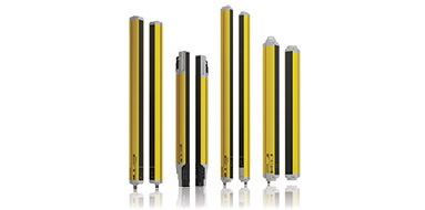
Optical safety devices
- Light curtains and light beams for optical protection in an opening or around a risk area.
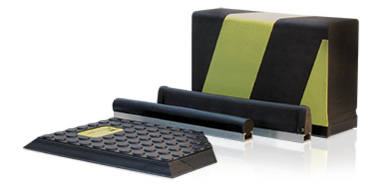
Safety contact edges, bumpers and safety mats
- Contact edges and bumpers for protection against crush injuries and safety mats for protection within dangerous areas.
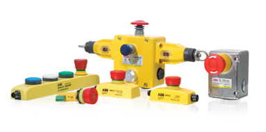
Emergency stops and pilot devices
- Emergency stops and pilot devices for dynamic and static safety circuits.
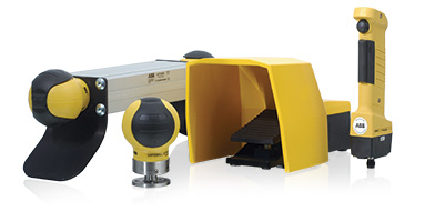
Safety control devices
- Safety control devices for start and stop dangerous machine movements
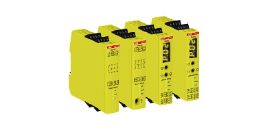
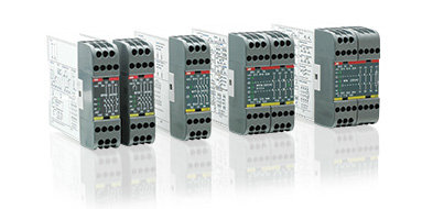
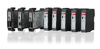
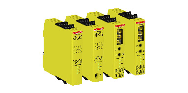
Safety relays
-
The Sentry safety relays are powerful and easy to use safety relays, suitable for all common types of safety applications.
The Sentry series contains basic models for simple applications and easy output expansion, as well as highly flexible models with extremely accurate timer functions.
Sentry safety relays are used in both simple and more advanced safety solutions when safety devices need to be monitored according to the requirements of functional safety standards.
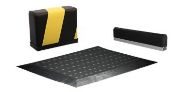
Pressure sensitive devices
-
Pressure sensitive devices detects when a pressure is being applied to them. For example when a person is being hit by the safety edge/bumper or is standing on the safety mat.
Safety edges and bumpers are used on moving doors or machine parts as protection against crushing injuries. Bumpers are used when longer stop times are needed. Safety mats are mainly used for area protection around dangerous machines.
Accessories
- Adapter units for connecting safety devices to our dynamic circuits and bus systems. Cables and connectors. Machine diagnostics tool.
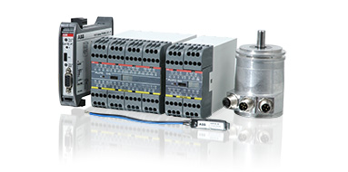
Programmable safety controllers
-
Compact, powerful and user-friendly...
The Pluto concept enables simple communication, programming and changes to the system. Pluto reduces installation time in many ways. For example, its safe bus simplifies the connection between cabinets in accordance with PL e/SIL3 and the AS-i models reduce cabling to a minimum while eliminating most risks of incorrect connection.
The programming software combines TÜV approved function blocks and ladder logic, and is very easy to use. Furthermore, up to 32 Pluto units can exchange data without having to configure or program the communication.
The Pluto systems consist of different types of Pluto Safety PLCs for all kinds of machine safety application, gateways for communication with other control systems and encoders for safe position determination of machine movements. 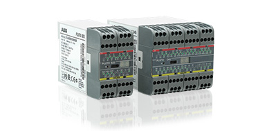
Pluto safety PLC
-
A compact, powerful and user-friendly safety PLC.
Pluto is a cost effective, powerful and compact safety PLC for all machine safety applications. Most safety devices on the market can be connected directly to Pluto and multiple safety sensors can be connected to a single input and still achieve the highest safety level. Programming is done easily in the accompanying software Pluto Manager.
Pluto is available in different models; simple models for smaller systems and models with bus communication for lager systems. Some of our Pluto models are adapted for AS-i . Models with analogue inputs are available as well.
Main benefits- Easy programming and still powerful
- Eliminates the need for extra module for speed monitoring for ex.
- Up to 32 Pluto can exchange data without extra programming
- Safe bus simplifies connection between cabinets in accordance with PL e/SIL3
- AS-i models simplify connection
- Extensive communication possibilities with HMI and PLCs
Main features
- Most Machine Safety functions inclusive speed monitoring and analog input monitoring
- Advanced programming possibilities
- Ladder and TÜV approved function blocks
- PL e/SIL 3
- Supports StatusBus
Gateways
-
Simple communication with external networks.
With the use of a Gateway device, Pluto can communicate with other control systems and thereby form a part of a larger network. The unit has a common interface with Pluto, i.e. the same cabling and the Pluto Manager software can be used for servicing and where necessary programming. There are different Gateway models available for different field buses.
Main benefits- Two-way communication
- Simplified programming with ready made function blocks
- Function blocks free of charge
Main features
Support for industry protocols:- Profibus DP
- DeviceNet
- CANopen
- PROFINET
- EtherNet/IP
- Modbus TCP
- EtherCAT
- Sercos III
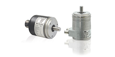
Encoders
-
Rotational absolute encoders for safe positioning.
Together with Pluto, rotational absolute encoders can be used for safe position determination of machine movements. The encoders are available in both single and multi-turn versions.
Main benefits- Easy safe communication with the Pluto Safety PLC
- Easy programming with ready made function blocks
- Safe position and speed monitoring
Main features
- Single and multi-turn versions
- Selectable resolution, up to 8192 positions/rev
- Up to PL e/SIL3
Accessories for programmable safety controllers
-
We offer a range of accessories for Pluto Safety-PLC such as cables, connectors, function blocks and identifier circuits (IDFIX).
IDFIX
IDFIX is an identification circuit that is unique to each device on the Pluto bus. It includes an identification code and makes it possible to distribute a PLC program in the network. There are four different versions: R, RW, DATA and PROG. In addition to the identification code, DATA may also include safety codes from the AS-i nodes in an AS-i system. PROG includes the current PLC program and is used with single-Pluto for program distribution.
Pluto Manager
- Pluto Manager is a software tailored for the safety PLC Pluto. Programming is done in ladder and together with the function block creates the structure of your safety functions. The software comes with predefined function blocks approved by TÜV to facilitate the work on designing the safety functions.
Pluto Manager gives you a structured overview of Pluto’s, gateways and peripheral components in large and small projects. It gives you an overview and control of the sensors and actuators, and the reactions between them. Pluto Manager also contains manuals for the software and hardware that are connected and needs to be handled through the program.
The interface gives the option to get the status directly from Pluto’s two bus options, AS-i and Pluto bus. There are also diagnostic functions and the option to export data.
Safety controllers
-
Vital safety controller and safety relays
We offer safety relays for all kinds of safety devices. Our safety relays have great flexibility and a wide range of input options. The relays are small and compact with an excellent reliability and safety level.
When several safety devices should control the same output, it is quite common to connect them in series. But to reach PL e, serial connection is not possible and each device should have its own safety relay. Vital offers the capability to exclusively control smaller machine safety systems that would otherwise have required a programmable controller or multiple safety relays. With the Vital safety controller, up to 30 safety devices can be connected in series to one Vital and still reach PL e. 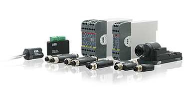
Vital Safety Controller
-
A simple way to reach the highest level of safety
When several safety devices should control the same output, it is quite common to connect them in series. But to reach PL e, serial connection is not possible and each device should have its own safety relay. Vital offers the capability to exclusively control smaller machine safety systems that would otherwise have required a programmable controller or multiple safety relays. With the Vital safety controller, up to 30 safety devices can be connected in series to one Vital and still reach PL e.
Main benefits- One Vital instead of several safety relays
- Easy to reach Cat 4
- Easier troubleshooting
- Easier connection
Main features
- Used with specific devices or traditional devices with Tina adpaters
- Models with one dynamic loop, two dynamic loops and logic, one dynamic loop and one 2 channel loop and logic
- LED indication for status of the device and the loop
- Info signal
- Devices with M12 connectors
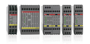
Safety relays
-
The RT series consists of universal relays that have the most common functions used in safety situations. These safety relays can supervise both your safety devices and the internal safety of your machinery. In addition you can select the safety level required for each installation.
The BT series consist of safety relays designed to connect safety devices, such as emergency stops, directly in the voltage supply circuit to the relay. Despite a compact width of 22.5 mm the relays are very powerful. These relays can also be used as expansion relays for Pluto to increase the number of outputs.
The JSB series consist of specialized safety relays for e.g. two hand devices with dual channel synchronization.
Main benefits- Less inventory since the universal relay is used for all type of safety devices
- Fast exchange thanks to removable terminal blocks
- Easier troubleshooting with information output
- Up to PL e/Cat 4, SIL3
- LED indication on front for fast diagnostic
Expansion relays
-
By connecting expansion relays from the E series to a safety relay it is easy to increase the number of safe outputs. This means that an unlimited number of dangerous machine operations and functions can be stopped from one safety relay.
The JSR series are used for expanding the outputs of safety relays. Stop signals can be delayed and outputs are also provided for function indication.
The BT series consist of safety relays designed to connect safety devices, such as emergency stops, directly in the voltage supply circuit to the relay. These relays can also be used as expansion relays for Pluto to increase the number of outputs.
Main benefits- Easy and safe expansion of safety outputs
- High switching capacity
- No need of external monitoring on BT50/51
- Width from only 22.5 mm
- Up to PL e/Cat 4, SIL3
Main features
- 4 safety outputs + 1 NC (Info)
- Up to 10A/250V switching capacity
- BT50 with 3 safety outputs: 3 NO + 1 NC (info)
- BT51 with 4 safety outputs: 4 NO
- Models with delayed safety outputs
Safety Timers
-
For time reset, time bypassing and inching
Main benefits
- Guaranteed maximum time
- Facilitates time reset, inching and time bypassing
Main features
- Timer selection, up to 40s
- 2 single NO outputs
- Removable terminal blocks
- Up to PL e/Cat 4, SIL3
Safety sensors, switches and locks
-
Sensors, switches and locks are used to control the gates and hatches around hazardous machinery, and to monitor the position of a machine.
Devices for the dynamic signal (Pluto safety PLC/Vital safety controller)- Eden non-contact sensor
- Magne magnetic process lock
- Dalton process lock with tongue
- Knox safety and process lock
Devices for all types of safety controllers
- Sense non-contact sensor
- MKey5 key switch
- MKey8 and MKey9 process lock
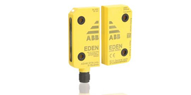
Eden
-
Highest safety level for harsh environments
Eden is a non-contact safety sensor for interlocked doors and safe position sensing. The safety sensor is used to assure that a machine stops when a door or hatch is opened. It can also be used to monitor if a robot is in a fixed position when someone enters the working area of the robot.
A non-contact safety sensor consists of two complementary parts that can sense each others presence without mechanical contact. This enables more flexible mounting compared to traditional mechanical switches. Eden is constantly communicating between the two parts and any failure will directly lead to a stop signal.
Main benefits- Flexible mounting, 360°
- Serial connection according to Cat. 4
- Withstands harsh environments
- Less cabling and control units with local reset function
- Appropriate when high motivation for fraud
- Easier troubleshooting with extensive LED indication, info signal and status bus
Main features- Sensing distance: 0 to 15 mm
- IP69K
- M12 connector
- High level code models
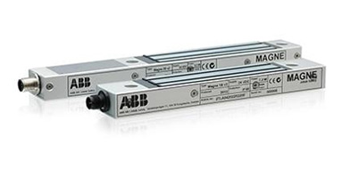
Magne
-
Robust magnetic process lock
Magne is an electromagnetic lock intended for electrical locking of doors and hatches with a holding force of up to 1500 N. Magne is usually used when access to the dangerous zone and the consequent stopping of the machine might only happen when specific conditions are met, at the end of the cycle for example.
Magne 1 and 3 are non-safe locks and must be associated to a safety interlocking device in safety applications.
Magne 2 integrates an Eden safety sensor and the interlocking function can reach up to a PLe/SIL 3.
Magne 1B, 2B & 3B have all an integrated permanent magnet which holds the door closed when no power is supplied.
Main benefits
- Larger mounting tolerances than mechanical locks facilitates installation.
- All the advantages of the integrated Eden safety sensor with Magne 2.
- Extensive indication reduces downtime.
- Less wear than a mechanical lock since there are no moving parts.
Main features
- Less wear than mechanical lock
- Holding force up to 1500 N
- Up to PLe/SIL 3 with only one device
- M12 connectors speed up installation
- Possible to connect in series with Eden sensors and Tina units
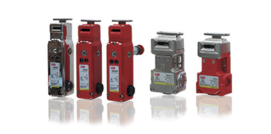
MKey
-
Simple and robust key switches
MKey safety switches are intended for detecting the position of moving guards. They are designed to fit the leading edge of sliding, hinged or lift off machine guards. MKey switches have rotary heads which provides ease of mounting and offer different actuator entry positions.
The MKey switches are available in several versions to meet different needs. Depending on the environment where the switch will be used, different material can be chosen. For extra durability, stainless steel versions are available. For use in hazardous areas where explosive conditions exists, versions approved by ATEX and IECEx are also available.
Main benefits- Easy mounting with rotating head
- Stainless steel models for extra durability
- EX-proof models
Main features
- Plastic, plastic with stainless steel and totally stainless steel models
- Spring-lock and electro-magnetic lock models
- IP69K
- Model with escape release
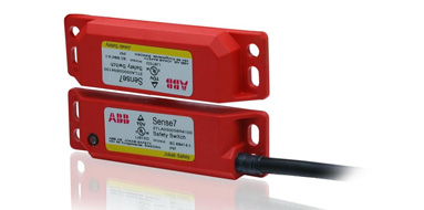
Sense
-
Simple non-contact switch for harsh environments
Sense is a non-contact safety sensor for interlocked doors and safe position sensing. The safety sensor is used to assure that a machine stops when a door or hatch is opened. It can also monitor that a robot is standing still in a monitored position when someone enters the robots working area.
A non-contact safety sensor consists of two complementary parts that can sense each others presence without mechanical contact. This enables more flexible mounting compared to traditional mechanical switches. Sense is constantly communicating between the two parts and any failure will directly lead to a stop signal. Sense works together with all of our control modules.
Main benefits- Easy to position with compact size
- Large tolerance to misalignment
- Withstands harsh environments
Main features
- 14 mm range
- PNP outputs, 2NO + 1NC
- UL approved polyester or stainless steel
- IP69K
- Different cable lengths
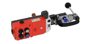
GKey safety lock
-
Mechanical safety lock for demanding environments
GKey is a robust safety lock with a die cast housing for hinged and sliding doors. GKey offers an interlocking function reaching PL e/SIL 3 with high level coding. Power is needed to unlock GKey which makes GKey a safety lock.
GKey is fitted with an rear escape release button, manual unlocking (auxiliary release) and offers four positions to integrate 22 mm pilot devices. By integrating the pilot devices into the switch housing, the number of external boxes for emergency stops, push buttons and selectors are reduced together with the cables and mounting brackets they would require. This results in a simplified installation, as well as less space used.
The simple construction with a sliding handle directly linked to the key and bolt - suitable both for hinged and sliding doors - minimizes the number of moving parts and the risk of mechanical problems.
Accessories for sensors, switches and locks
-
On this page you can find information about accessories for the following products:
- Eden non-contact sensor
- Magne magnetic process lock
- Dalton process lock with tongue
- Knox safety and process lock
- Sense non-contact sensor
- MKey5 key switch
- MKey8 and MKey9 process lock
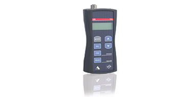
- Fixa handheld terminal for sensors
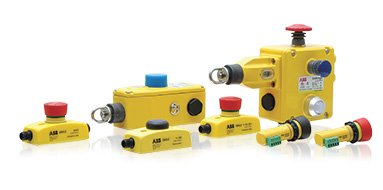
Emergency stops and pilot devices
- An emergency stop device is used to permit anyone to stop machinery if it breaks down or if someone is in danger. We offer different types of traditional mushroom head type emergency stop for different types of mounting and environment. We also offer grab wire emergency stops which allow emergency command from any point along the installed wire length.
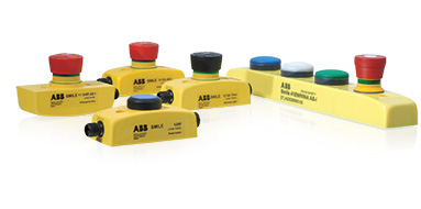
Smile
-
Compact emergency stops and push-button boxes
Smile emergency stop is a small and easy to install emergency stop. The size of the device makes it possible to be installed wherever you want. It comes with M12 connection or cable, and the centralised mounting holes makes it especially easy to mount on aluminum extrusions.
Smile 41 push-button box gathers up to four push-buttons and emergency stop button in a single compact device. Two series of Smile 41 is available - a set of models for standard Pluto and another set of models adapted for AS-i Safety.
Main benefits- Compact housing makes it easy to place
- Easy connection
- Easy troubleshooting
- Serial connection in accordance with Cat 4 (Tina models)
Main features
- Compact size
- M12 connector(s)
- LED indication
- Tina models (for dynamic safety circuits)
- AS-i models
- StatusBus models (Smile Tina)
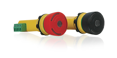
INCA
-
Emergency stop for enclosure installation
INCA is an illuminated emergency stop for panel mounting. It is designed for installation in 22.5 mm holes in equipment cabinets and the connection is easily made via a removable terminal. With its very compact dimensions, INCA takes very little space in the cabinet.
Main benefits- Easy connection
- Easy troubleshooting
- Serial connection in accordance with Cat 4
Main features
- Removable terminal block
- LED indication
- Tina models
- Model with black button
- Models with StatusBus (INCA Tina)
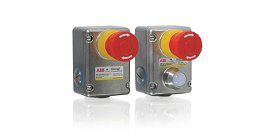
Estrong
-
Emergency stop for harsh environments
EStrong is an emergency stop designed to provide a robust unit in exposed and severe environments. The unit has a stainless steel enclosure that withstands high pressure and high temperature wash-down. It is therefore ideally suited for industries that have special demands, such as food processing or chemical industry.
Main benefits- Robust construction
- High sealing
- Models for explosive environments
Main features
- Stainless steel
- IP69K
- EX proof models
- Models with LED status indication
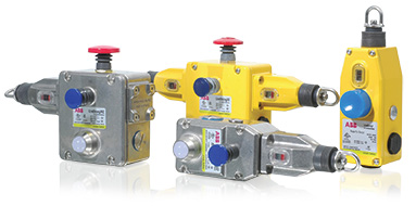
LineStrong
-
Grab wire safety switch
LineStrong Emergency stops are grab wire safety switches designed to be mounted on machines and sections of conveyors which cannot be protected by guards. In contrast to traditional mushroom head type Emergency stops, LineStrong can initiate the emergency command from any point along the installed wire length, and thereby provide robust emergency stop protection for exposed conveyors and machines.
Main benefits- High level of safety
- Up to 200m wire with one switch
- Reliable mechanical connection
- Robust construction
Main features
- Stainless steel models
- Ex proof models
- Switching in 2 directions
- Models with integrated e-stop button
Accessories for Emergency Stops and Pilot Devices
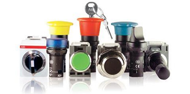
Pilot devices
-
The complete offering
From the smallest inside component to the outer tough shell, ABB's pilot devices are pieces of engineering ingenuity. Reliable, flexible and available worldwide - just as ABB.
A quality experience throughout.Main benefits
- Extremely robust and reliable
- Identical look outside the panel makes mixing compact and modular range easy
- A complete offering to meet any customer need.
Main features
- High IP ratings
- Fulfills major international standards.
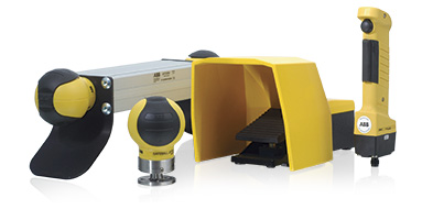
Safety control devices
- Safety control devices are used to directly start and stop dangerous machine movements. We offer several different types of control devices to meet different needs.

Safeball
-
Innovative and ergonomic machine control
Safeball consists of a spherical ball containing two embedded pushbutton switches, one on each side of the ball. To be able to start and operate a machine both buttons must be activated. The risk of unintentional activation is thereby minimized and the device is simple and ergonomic to use.
Safeball can be utilised for either one-hand or two-hand applications. For a two-hand control device the operator needs to have a Safeball for each hand to be able to operate a machine. If one or more pushbuttons are released a stop signal is given to the machine.Main benefits
- Egonomic with several grip possibilities
- Low but distinct activation force
- Flexible mounting
- Easy connection with AS-i models
Main features
- 1 NO + 1 NC
- Several cable lengths
- Up to PL e/Cat 4
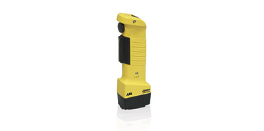
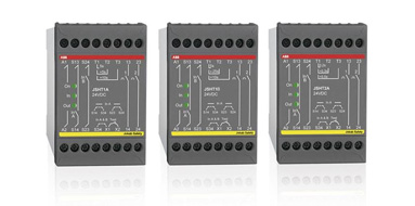
HD5 and JSHD4
-
Ergonomic and adaptable three-position device
Three-position devices (or hold-to-run devices) can be used for troubleshooting, programming and test running in situations where no other protection is available or feasible. With a three-position device the operator can either press harder in an emergency or release the device to stop the machine.
Main benefits- Ergonomic
- Adaptable
- Easy safe connection with AS-i
- Anti-tampering option for more safety
- Modular device
- Up to 2 extra buttons
- M12 and other types of connection
- Model with emergency stop button
- Up to PL e/Cat 4
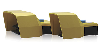
Fox
-
Robust and safe foot-operated safety switch
A foot-operated safety switch is used when the operator needs to start and stop a machine in a safe way while both his hands are busy, holding a work piece for example.
Main benefits- Robust construction
- High level of safety
- Variety of models
- Die cast aluminium alloy
- Protective cover
- Two or three position function
- Single and double pedals
- Duplicated contacts
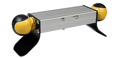
JSTD25
-
Ergonomic and adaptable two-hand station
A two-hand device can be used when it is necessary to ensure that the operator is outside and must be prevented from reaching into the hazardous area. The JSTD25 replaces the traditional two-hand device. With a JSTD25 two-hand control station you have a prepared two-hand unit that is easy to install, while utilising the good ergonomics of the Safeball.
Main benefits- Ergonomic
- Shorter safety distance thanks to the Safeball™
- Easy installation
- Easy mode selection with integrated sensor
- 1 NO + 1 NC / Safeball
- M12 connection available
- Possibility of Emergency stop button
- Model with Eden sensor integrated
Accessories for Safety Control Devices