HAWE

- Offer Profile
- Welcome to the world of
HAWE
HAWE is a leading manufacturer of technologically advanced, high-quality hydraulic components and systems. About 2.100 employees contribute to the company's success at our headquarters in Munich, at our five other plants in Germany, and in our international sales network with thirteen subsidiaries in Europe, America and the Asia-Pacific region.
Product Portfolio
Pumps
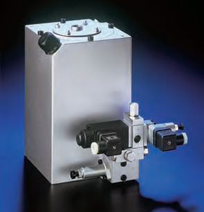
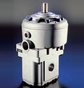
Compact hydraulic power packs
- Design:
Oil immersed hydraulic
power pack for intermittent
service (S3-service)
pmax:
Radial piston pump 700 bar
Gear pump 180 bar
Qmax:
Radial piston pump
approx. 20.1 lpm
(Vg = 7.2 cm3/rev)
Gear pump
approx. 20.4 lpm
(Vg = 7.9 cm3/rev)
Vusable max:
8 l
These ready for connection hydraulic power packs are intended for intermittent operation (S3) and used to supply pressurized fluid to consumers with low fluid demand, such as for jigs or machine tools
or general machine building.
The power pack consists of a housing (tank) with integrated motor and pump. The housing of size 2, 3, and 4 features also a filling gauge, enabling visual control of the fluid level even during operation. The
electrical connection takes place via an integrated terminal box.
Complete hydraulic control systems can be created by directly mounting various combinations of connection blocks and valve banks to the hydraulic power pack. Float switch as well as temperature switch are available as option for the optimal supervision.
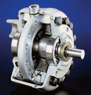
Radial piston pumps
- Design:
Individual pump
Pump complete with motor
Hydraulic power pack
pmax:
700 bar
Qmax:
91.2 lpm
(Vg = 64.18 cm3/rev)
Vmax tank:
approx. 470 l
The radial piston pumps consist of radially arranged, valve controlled pump cylinders. Higher delivery flows can be created by stacking of up to 6 radials on a common shaft. The pump is usually driven by an electric motor, which is connected with the pump by means of a bell housing and a coupling.
The closed pump housing permits ”in tank” installation (hydraulic power pack) as well as the common external pump/ motor installation (pump
with motor). The possibility of a radial piston pump with several pressure outlets (several equal or differing delivery flows) is particularly innovative.
Type RG utilizes slide bearings and is intended for extreme application conditions to increase the service life. Complete hydraulic control systems
can be created by directly mounting various connection blocks and valve banks to the cover plate of the hydraulic power pack.
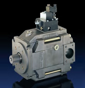
Axial piston machines
- Design:
Individual pump
Pump combination
pmax:
350 bar (continuous)
420 bar (peak)
Qmax:
65 ... 392 lpm
(1450 rpm)
Vg max:
45 ... 270 cm3/rev
The InLine variable displacement pump type V30D and V30E work according to the swash plate principle and are intended for open circuit operation
in industrial and mobile hydraulics. There is also an option for a thru-shaft for flange mounting additional variable and fixed displacement pumps. Type V30E is intended as successor of V30D, where the completely new development allowed to realize state of the art pump design. This concerns primarily the optimization of self-suction speed rating, minimized noise level, weight, and pulsation as well as increased service life.
These pumps are suited for a wide range of applications due to their low running noise and various pump controllers. Hydraulic circuits where several outlet flows are required can be fed either by one individual pump or a multiple pump. Main benefit of these pumps are the sturdy design, the good
performance/weight ratio, long service life due to oversized bearings, and the swash plate angle indicator.
Dual stage pumps
- Design:
Individual pump
Pump complete with motor
Hydraulic power pack
pmax:
700 bar (radial piston pump)
150 bar (gear pump)
Qmax:
Radial piston pump
91.2 lpm (high pressure)
(Vg = 64.18 cm3/rev)
Gear pump
135 lpm (low pressure)
(Vg = 89.6 cm3/rev)
Vmax tank:
approx. 470 l
Dual stage pumps consist of a high pressure section (radial piston pump, HP) and a directly coupled low pressure section (gear pump, LP). The
pump is usually driven by one single electric motor, which is connected with the dual stage pump by means of a flange and a coupling. Complete hydraulic control systems (e.g. for presses) can be created by directly mounting dual stage valves or valve banks to the cover plate of the hydraulic power pack.
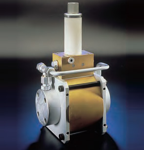
Air driven hydraulic pumps
- Design:
Individual pump
Hydraulic power pack
pmax hydr:
160...1500 bar
pmax air:
10 bar
Qmax:
0.9...12 lpm
These hydraulic pumps are reciprocating, valve controlled plunger pumps. They are basically oscillating pneumatic/hydraulic pressure intensifiers which are available in three sizes. These pumps stop
automatically when the opposing forces on the pneumatic side of the piston are in equilibrium with the forces on the hydraulic side. Likewise the pumps will start when the forces are unequal. This force equivalent also determines the cycle frequency.
The hydraulic pumps type LP are available in various versions e.g. pump only, hydraulic power pack with tank or as turn-key power pack with the required directional valves directly mounted. These pumps are commonly used in hazardous areas where electric
motor drive pumps may cause fire or explosion such as in dye works, mining, pyrotechnic industry, petroleum refineries etc. These pumps also perform well in laboratory presses, jigs or lubrication
applications.
Hand pumps
- Design:
Single acting hand pump
Double acting hand pump
pmax:
80 ... 600 bar
Vmax:
4 ... 64 cm³/stroke
The hand pumps type H are available in single acting and double acting versions. The single acting design pumps in one lever direction only, the reverse motion performs the suction stroke.
The double acting design pumps and intakes simultaneously in both lever directions. In one particular design, the suction side may be charged with up to 150 bar.
The lever mechanism may be protected from harsh environments if desired, and may incorporate a drain valve (connecting P ® S), a pressure limiting valve or a tank. These additional options enable the use of this pump in a wide array of application.
Valves
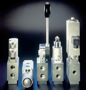
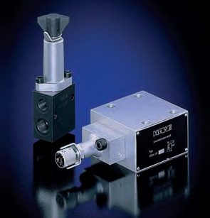
Directional spool valves
- Design:
Individual valve for
pipe connection or
manifold mounting
Actuation:
Solenoid
Manual
• With autom. spring return
• With detent
Mechanical
• Roller head
• Pin head
Pressure
(only or combined
with manual actuation)
• Hydraulic
• Pneumatic
pmax:
200 ... 400 bar
Qmax:
12 ... 100 lpm
The directional spool valves with optional pressure limiting valve type SG and SP are available in 5 sizes either for pipe connection (type SG) or manifold mounting (type SP).
They are widely used to control the direction of movement of hydraulic consumers e.g. motors or cylinders. The sturdy design and a wide range of different actuations enable utilization of these valves in many applications such as mobile hydraulics or on ships.
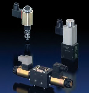
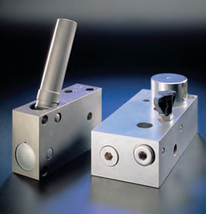
Directional seated valves
- Design:
Individual valve for
pipe connection
Individual valve,
Manifold mounting
Actuation:
Solenoid
Hydraulic
Pneumatic
Manual
pmax:
400 bar
Qmax:
20 ... 70 lpm
The directional cone seated valves types BVG, BVE, and BVP are 2/2- and 3/2-way directional valves which are available in two sizes. Size 1 valves
feature optionally a version with industrial standard connection pattern NG6 (type NBVP) and a version with 4/3-way function. All ports are equally pressure resistant due to an internal, static pressure balance.
The valves may be connected directly via pipes (type BVG), mounted at customer furnished manifolds (type BVP and BVE) or industrial standard sub-plates (type NBVP). Various actuation modes (BVE only with solenoid actuation) enable use of these valves in a
wide field of applications.
Additional elements for ports P, R, A, and B (e.g. screw-in orifices, restrictor check valves) can be incorporated in the valve body and allow tailoring he valve exactly to the special requirements of the
customer.
Pressure valves
- Design:
Individual valve for
pipe connection
Individual valve
Manifold mounting
Adjustability:
Tool adjustable
Manually adjustable
pmax P:
300 ... 400 bar
pmax A:
250 ... 400 bar
Qmax:
120 lpm
The task of pressure reducing valves in a hydraulic circuit is to maintain a rather constant outlet pressure despite a higher and changing inlet pressure. These valves are usually used when a secondary circuit has to be fed with a lower but constant pressure level by a main (primary) circuit with a higher and varying pressure level.
These valves are either directly controlled (type ADM) or hydraulically piloted (type VDM).
There is a design related permanent leakage flow apparent at L, which has to be led back to the tank via a de-pressurized line. A reversal of the direction of flow is possible up to approx. 50% of Qmax. A by-pass check valve has to be provided for higher reversed flow. The pressure reducing valves type ADM feature a override compensation i.e. acting like a pressure limiting valve, if the pressure on the secondary side exceeds the set pressure e.g. due
to external forces.

Metering valves
- Design:
Individual valve for
pipe mounting
Screw-in valve
Adjustability:
Manually adjustable
(handle, adjusting knob)
Tool adjustable
pmax:
500 ... 630 bar
Qmax:
50 lpm
The throttle and shut-off valves types AVT, AV, and CAV, which can be completely blocked, are available in various sizes and belong to the flow valve group. Versions AV...E and CAV are screw-in valves. They generate a pressure drop between inlet and outlet to control the speed of cylinders in accumulator circuits, the flow in control circuits, or can function as a
safeguard for a pressure gauge.
The throttles type AV.. restrict the flow via an annular gap i.e. a cone enters a valve seat hole (needle valve. Throttles type CAV create backpressure by means of a slot with a constant width, where the area of opening varies proportionally with the distance of the
adjustment travel. Valves using this throttling principle (slot type throttle) are less sensitive to micro-contamination. Additional versions are available with an integrated check valve to enable free flow in the opposite direction.
Check valves
- Design:
Individual valve for in-line installation
pmax:
500 bar
Qmax:
15 ... 160 lpm
These check valves type B are available in three housing designs with internal and/or external thread, enabling in-line installation for any requirement. It is also possible to use these valves as foot valves in the suction line of pumps due to their low response pressure.
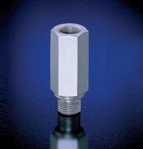
Accessories & Clamps
Connectors & others
- pmax: 350 ... 700 bar
Many devices like e.g. pressure gauges, pressure switches, accumulators etc. are integrated in hydraulic circuits by means of fittings. A wide range
of fittings enables mounting of these devices in all kind of installation positions to hydraulic power packs and valves from HAWE. Reducers help to combine them with other devices.
There are two types of filters, which serve to protect hydraulic devices, preferably directional valves from coarse so-called vagabond, contamination which occur sometimes. The screen filters are to restrain coarse particles whereas wire mesh filters should be used for hydraulic circuits with rather low flow only.
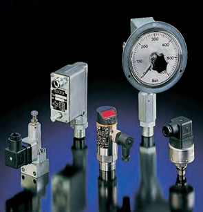
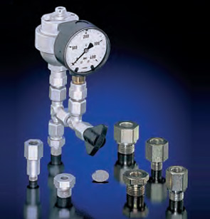
Pressure switches
- pmax: 0 ... 700 bar
pmax: 0 ... 1000 bar
Electro-hydraulic pressure switches are devices, which, when set under pressure close or open electrical contacts. They are widely used in applications where it is intended that, once a pre-set pressure is achieved and exceeded, an electrical switching command or signal should be triggered
for further working cycles.
Many different versions (with pressure setting on a dial, with main and secondary switch, screw-on pressure switches) enable their use in many applications.
There is a design related difference of 8 ... 20 % between the upper switching point and the lower switching point. Only the electronic pressure switch type DG 5 E gives provision to select two independent switch points and to set the hysteresis.
Type DT is an analogous pressure sensor.

Accumulator
- pmax:
500 bar
V0 max:
1.95 dm3
The diaphragm type hydraulic miniature accumulators type AC are available in two sizes. The smaller accumulators with a volume of 0.013 dm3 bzw. 0.040 dm3 are used to compensate temperature dependent volume variations, possible losses due to leakage, or to dampen oscillations in circuits with pressure difference controlled devices.
The bigger ones with volumes between 0.32 dm3 and 1.95 dm3 as are mainly used to assist the pump delivery flow or as source of pressurized oil for emergency actuations.
These accumulators may be integrated in differing hydraulic systems e.g. hydraulic clamping systems, in various installation positions by means of a wide range of fittings.
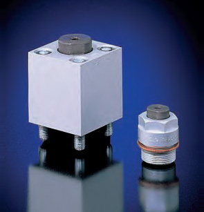
Clamping cylinders
- Design:
Screw-in version
Manifold mounting
pmax:
500 bar
Fmax:
60000 N
Hydraulic clamps type HSE and HSA are single-acting power elements equipped with return springs, which are used in hydraulic fixtures where only a very restricted space is available for the generation of high forces with limited piston movement. The type HSE is designed as a screw-in cylinder whereas type HSA is manifold mounting. These clamps are available, depending on application with piston diameters between 12 and 40 mm and strokes between 2 and 25 mm. They are mainly used for
clamping work pieces, slides and guides, indexing round tables and for bending punching and cutting purposes.
Electronics
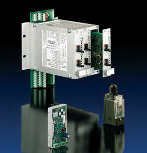
Plugs, proportional amplifiers & others
- There is a wide range of electronic components for the
control of common on/off and proportional solenoids available. The range
consists of e.g. electronic amplifiers as modules, cards, versions
integrated in the plug for single or twin solenoids or for pressure
switches.
A power supply for 230V DC / 24V DC solenoid valves is also available. All these components are designed for HAWE solenoid valves.
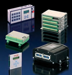
Programmable logic controls
- The programmable logic valve control type PLVC is
intended for the control of complex hydraulic circuits. Movements with
various pressure, speed, and acceleration profiles, within predefined
ranges, can be controlled and saved. It can be descirbed as a user
programmable PLC with built-in amplifiers for proportional valves.
Analogous, digital and components connected via CAN-Bus (e.g. pressure sensors, joy-sticks, etc.) can be utilized for control or closed loop tasks, connected via cable or wireless. This high degree of flexibility is achieved by:
• Modular concept with various extensions and add-on's (basic and extension module, diagnosis display, CAN-Bus-power relays)
• Flexible programming
• Various interfaces (RS 232, CAN-Bus, Profi-Bus)
• Free parameter setting of all in- and out-puts
• Remote diagnosis via modem and mobile telephone
• Software function blocks (PLC programs)
• Remote control module
Main field of application is with machines for construction, lifting, logging, machine tools, and presses.