HEIDENHAIN

- Offer Profile
- Increased productivity
with HEIDENHAIN
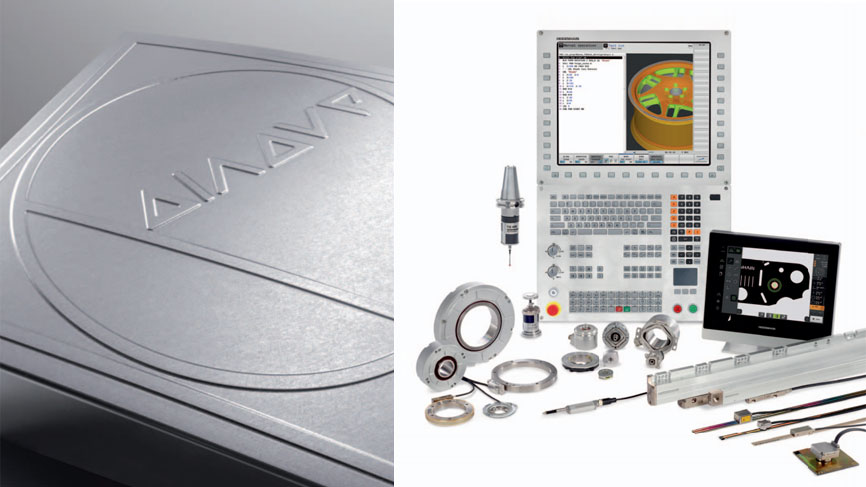
Products from HEIDENHAIN ensure that machines and plants work productively and efficiently. Since 1948, when the company began anew in Traunreut, HEIDENHAIN has shipped over 4.5 million linear encoders, over eight million rotary and angular encoders, 450,000 digital readouts and nearly 220,000 TNC controls. Now and in the future, this expertise provides the assurance that HEIDENHAIN was the right choice.
Product Portfolio
Length Measurement
- Linear encoders
Sealed linear encoders are protected from dust, chips and splash fluids and are ideal for operation on machine tools.
Exposed linear encoders operate with no mechanical contact between the scanning head and the scale or scale tape. Typical areas of application for these encoders include measuring machines, comparators and other precision devices in linear metrology, as well as production and measuring equipment, for example in the semiconductor industry.
With incremental linear encoders, the current position is determined by starting at a datum and counting measuring steps, or by subdividing and counting signal periods. Incremental encoders from HEIDENHAIN feature reference marks, which must be scanned after switch-on to reestablish the datum. This process is especially simple and fast with distance-coded reference marks.
Absolute linear encoders require no previous traverse to provide the current position value. The encoder transmits the absolute value through the EnDat interface or another serial interface.
Length gauges from HEIDENHAIN feature integral guideways for the plunger. They are used to monitor measuring equipment, in industrial metrology, and also as position encoders. 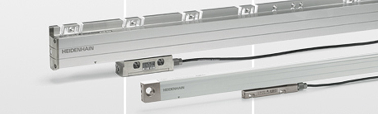
Sealed Linear Encoders
-
Sealed linear encoders from HEIDENHAIN are protected from dust, chips and splash fluids and are ideal for operation on machine tools.
- Accuracy grades as fine as ± 2 μm
- Measuring steps as fine as 0.001 μm
- Measuring lengths up to 30 m (to 72 m upon request)
- Fast and simple installation
- Large mounting tolerances
- High acceleration loading
- Protection against contamination
Sealed linear encoders are available with
- Full-size scale housing
– For high vibration loading
– Up to 30 m measuring length - Slimline scale housing
– For limited installation space
– Up to 1 240 mm measuring length, up to 2 040 mm with mounting spar or tensioning elements
The aluminum housing of a HEIDENHAIN sealed linear encoder protects the scale, scanning carriage, and its guideway from chips, dust, and fluids. Downward-oriented elastic lips seal the housing. The scanning carriage travels along the scale on a lowfriction guide. It is connected to the external mounting block by a coupling that compensates unavoidable misalignment between the scale and the machine guideways.
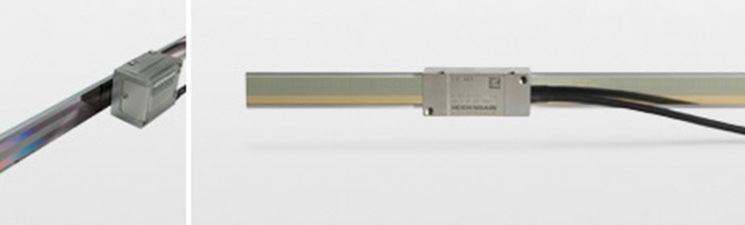
Exposed Linear Encoders
- Exposed linear encoders are designed for use on machines
and installations that require especially high accuracy of the measured
value.
Typical applications include:- Measuring and production equipment in the semiconductor industry
- PCB assembly machines
- Ultra-precision machines
- High-accuracy machine tools
- Measuring machines and comparators, measuring microscopes, and other precision measuring devices
- Direct drives
Exposed linear encoders consist of a scale or scale tape and a scanning head that operate without mechanical contact. The scale of an exposed linear encoder is fastened directly to a mounting surface. The flatness of the mounting surface is therefore a prerequisite for high accuracy of the encoder.
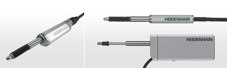
Length Gauges
- Length gauges from HEIDENHAIN offer high accuracy over
long measuring ranges. These sturdily made gauges are available in
application-oriented versions.
They have a wide range of applications in production metrology, in multipoint inspection stations, measuring equipment monitoring, and as position measuring devices.
A number of arguments speak for HEIDENHAIN length gauges:
Large measuring ranges
HEIDENHAIN length gauges are available with measuring lengths of 12 mm, 25 mm, 30 mm, 60 mm or 100 mm so that you can measure very different parts in one measuring setup and avoid frequently changing setups with expensive gauge blocks or masters.
High accuracy
The high accuracy specified for HEIDENHAIN length gauges applies over the entire measuring length. Whether the part measures 10 or 100 mm, its actual dimension is always measured with the same high quality. The high repeatability of HEIDENHAIN length gauges comes into play during comparative measurements, for example in series production.
Robust design
HEIDENHAIN length gauges are built for an industrial environment. They feature consistently high accuracy over a long period of time as well as high thermal stability. They can therefore be used in production equipment and machines. .
Angle Measurement
- For angle measurement, HEIDENHAIN provides a large
selection of encoders that covers the entire range of accuracy requirements.
Angle encoders
The term angle encoder is typically used to describe encoders that have an accuracy of better than ± 5" and a line count above 10000. These devices are used in applications such as NC rotary tables, swivel heads of machine tools, dividing apparatuses, high-precision angle measuing tables, precision devices in angular metrology, antennas and telescopes.
Rotary encoders
Rotary encoders from HEIDENHAIN serve as measuring sensors for rotary motion, angular velocity and also, when used in conjunction with mechanical measuring standards such as lead screws, for linear motion. Application areas include electrical motors, machine tools, printing machines, woodworking machines, textile machines, robots and handling devices, as well as various types of measuring, testing, and inspection devices.
With incremental angle encoders and rotary encoders, the current position is determined by starting at a datum and counting measuring steps, or by subdividing and counting signal periods. Incremental encoders from HEIDENHAIN feature reference marks, which must be scanned after switch-on to reestablish the datum. Incremental rotary encoders with commutation signals supply the angular shaft position value - without requiring previous traverse - with sufficient accuracy to correctly control the phases of the rotating field of a permanent-magnet three-phase motor.
Absolut angle encoders and rotary encoders require no previous traverse to provide the current position value. Singleturn encoders provide the current angular position value within one revolution, while multiturn encoders can distinguish between revolutions. Absolute angle encoders and rotary encoders from HEIDENHAIN provide the position values over an EnDat, SSI, PROFIBUS-DP or other serial data interface. The EnDat PROFIBUS-DP bidirectional interfaces enable automatic configuration of the higher-level electronics and provide moitoring and diagnostic functions. With programmable rotary encoders, the user can adjust various encoder functions and parameters from a PC with provided software.
Magnetic Modular Encoders
The robust ERM magnetic modular encoders are especially suited for use in production machines. Their large possible inside diameters as well as the small dimensions and compact design of the scanning head predestine them for:- The C axis of lathes
- Spindle orientation on milling machines
- Auxiliary axes
- Integration in gear stages
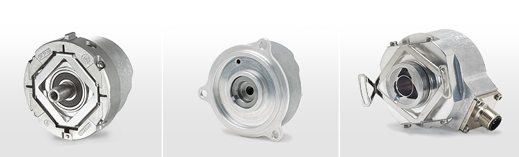
Rotary Encoders
- Mounting variants
In rotary encoders with integral bearing and stator coupling, the graduated disk of the encoder is connected directly to the shaft to be measured. The scanning unit is guided on the shaft via ball bearings, supported by the stator coupling. During angular acceleration of the shaft, the stator coupling must absorb only that torque resulting from friction in the bearing, thereby minimizing both static and dynamic measuring error. Moreover, the coupling mounted on the stator compensates axial motion of the measured shaft. Other benefits of the stator coupling are:- Simple mounting
- Short overall length
- High natural frequency of coupling
- Hollow-through shaft possible
Rotary encoders without integral bearing operate without friction. The two components - the scanning head and the scale disk, drum, or tape - are adjusted to each other during assembly. The benefits are:- Large diameter of hollow shaft
- For high shaft speeds
- No additional starting torque
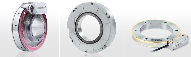
Angle Encoders
- HEIDENHAIN angle encoders are characterized by high
accuracy values in the arc second range and better.
Examples for application:- Rotary tables on machine tools
- Swivel heads on machine tools
- C axes on lathes
- Gear-testing machines
- Printing units of printing machines
- Spectrometers
- Telescopes
Angle encoders with integral bearing, hollow shaft and integrated stator coupling
Because of the design and mounting of the stator coupling, it must only absorb that torque caused by friction in the bearing during angular acceleration of the shaft. RON, RPN and RCN angle encoders therefore provide excellent dynamic performance. With an integrated stator coupling, the stated system accuracy also includes the deviations from the shaft coupling. Further advantages:- Compact size for limited installation space
- Hollow shaft diameters up to 100 mm for leading power cables, etc.
- C axes on lathes
- Simple mounting
- Angle encoders with integral bearing, for separate shaft coupling
Angle encoders without integral bearing
The ERA and ERO angle encoders without integral bearing (modular angle encoders) are intended for integration in machine elements or apparatuses. They are suited for the following requirements:- Large hollow shaft diameter (up to 10 m with a scale tape)
- High shaft speeds up to 40000 rpm
- No additional starting torque from shaft seals
- Segment solutions
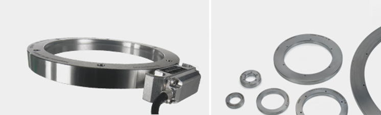
Magnetic Modular Encoders
- The robust ERM magnetic modular encoders are especially
suited for use in production machines. Their large possible inside diameters
as well as the small dimensions and compact design of the scanning head
predestine them for:
- The C axis of lathes
- Spindle orientation on milling machines
- Auxiliary axes
- Integration in gear stages
Accuracy
C axes on lathes are typically used for the machining of bar-stock material. Here the graduation of the ERM modular encoder is usually on a diameter that is twice as large as the workpiece to be machined. The accuracy and reproducibility of the ERM also achieve suffi cient workpiece accuracies for milling operations with lathes (classical C-axis machining).
Measuring standard
HEIDENHAIN encoders incorporate measuring standards of periodic structures known as graduations. Magnetic encoders use a graduation carrier of magnetizable steel alloy. A write head applies strong local magnetic fields in different directions, so that a graduation consisting of north poles and south poles is formed with a grating period of 400 µm (MAGNODUR process). Due to the short distance of effect of electromagnetic interaction, and the very narrow scanning gaps required, finer magnetic graduations are not practical.
Controlling Machine Tools
- The TNC Controls for Milling Machines and Machining
Centers:
- Form a complete product line with their various features
- Control machines with up to 13 axes
- Their plain-language programming capability is suited for the workshop floor
- Can also be programmed externally
- Are also suited for automated production
- Are the correct choice for everything from simple milling procedures to high-speed milling
- Ideal for both CNC and cycle lathes
- Enables the familiar manual production of simple workpieces
- Supports programming with many cycles
- Its smart.Turn feature offers form- and graphics-supported programming for complicated workpieces
- Performs complementary milling and drilling operations in a single fixture
- Also supports vertical lathes
- Suited for digital or analog drive control
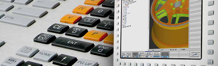
Milling
- The TNC controls for milling, drilling, boring
machines and machining centers
For almost 30 years, TNC controls have been proving themselves in daily use on milling machines, drilling and boring machines, and machining centers. This success is due in part to their shop-oriented programmability, but also to their compatibility with programs of the predecessor models.
TNC contouring controls from HEIDENHAIN for milling, drilling, boring machines and machining centers cover the whole range of applications: From the simple, compact TNC 320 three-axis control to the iTNC 530 (up to 13-axis spindle) - there's a HEIDENHAIN TNC control for nearly every application.
Not every machining task requires a contouring control and all the advanced features of a CNC machine. In many cases a straight cut control and the features offered on the TNC 124 are fully adequate

Turning
- MANUALplus 620 – The Contouring Control for CNC and
Cycle Lathes
For many years now, the MANUALplus has been proving itself in daily use on cycle lathes and is characterized particularly by convenient manual machine operation. Application-oriented cycle programming enables the machinist to create and edit programs rapidly and effi ciently on the lathe.
The introduction of the MANUALplus 620 extends the area of application to single-spindle CNC lathes. With the smart.Turn operating mode, HEIDENHAIN has made yet another step forward toward greater ease of use. Easily understandable program entry in forms, default setting for global values, selection options and straightforward graphic support ensure fast and easy operation. The new smart.Turn interface is based on the proven HEIDENHAIN DIN PLUS: smart.Turn creates DIN PLUS programs and provides both the NC programmer and the machine operator with all relevant information during program run.
The MANUALplus 620 is designed for lathes with spindle, one slide (X and Z axis), C axis or positionable spindle and driven tool. It is suited for horizontal and vertical lathes with simple tool holders or with tool turrets. Cycle lathes are usually used for smaller and mid-size production batches. The operator of a MANUALplus 620 profits from the quickly learned cycle programming, with which workpieces can be machined quickly and efficiently. And when requirements increase and you machine complex tasks with your lathe, you then create your NC programs with the new smartTurn programming mode. The smartTurn programming mode of operation is the basis for NC programming on CNC lathes.
This new type of NC programming is also mastered quickly, since the machinist does not have to deal with G or M functions, or with structuring a machining block. smartTurn uses the easy-to-learn form entry method of programming
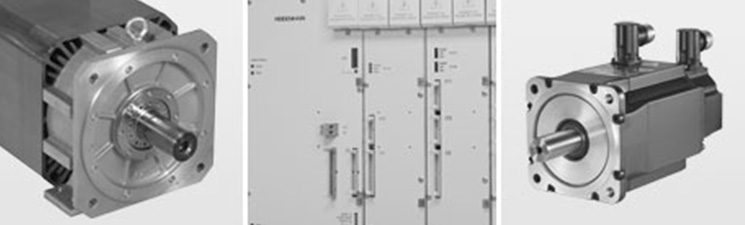
Drive Technology
- High surface definition, high contouring accuracy of the
finished workpiece, and short machining times - these requirements can be
met only with digital drive concepts. For integrated drive control,
HEIDENHAIN offers the iTNC 530. Either compact or modular inverters are
available, depending on the type of machine.
The compact inverters contain the power stage for up to 3 axes or 4 axes plus spindle with spindle power ratings up to 15 kW.
With modular inverters, various power modules are available for axes and spindles, and power supply units with 22 kW to 55 kW. Modular inverters are designed for machines with up to 13 axes plus spindle with a spindle power rating up to 35 kW.
Feed motors of 1.5 Nm to 44 Nm and spindle motors of 5.5 kW to 30 kW are available for connection to HEIDENHAIN inverters.
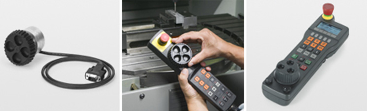
Accessories
- Electronical Handwheels
With the electronic handwheel from HEIDENHAIN, you can use the feed drive to make very precise movements in the axis slides in proportion to the rotation of the handwheel. As an option, the handwheels are available with mechanical detent.
HR 410 and HR 520 portable handwheels
The axis keys and certain functional keys are integrated in the housing. It allows you to switch axes or setup the machine at any time and regardless of where you happen to be standing. The HR 520 also features a display for the position value, the feed rate and spindle speed, the operating mode and other functions, as well as an override potentiometer for feed rate and spindle speed.
HR 130 and HR 150 panel-mounted handwheels
Panel-mounted handwheels from HEIDENHAIN can be integrated in the machine operating panel or be built-in at another location on the machine. Up to three HR 150 electronic handwheels can be connected through an adapter.
Setup and Measurement
- Tool and Workpiece Setup and Measurement
The TS workpiece touch probes from HEIDENHAIN help you perform setup, measuring and inspection functions directly on the machine tool.
Tool measurement on the machine shortens non-productive times, increases machining accuracy and reduces scrapping and reworking of machined parts. With the tactile TT touch probes and the contact-free TL laser systems, HEIDENHAIN offers two completely different possibilities for tool measurement.
Measuring Systems For Machine Tool Inspection and Acceptance Testing
Machine tool performance from the point of view of compliances to tolerances, surface defi nition, etc., is determined essentially by the accuracy of machine movement. 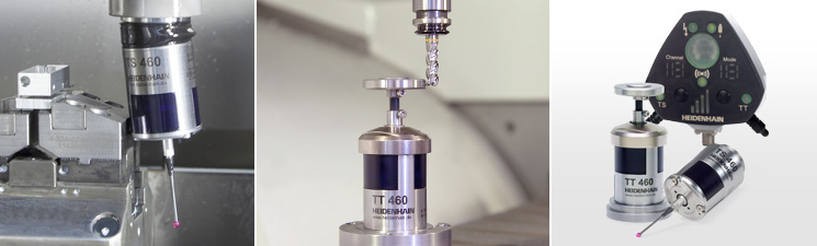
Touch Probes
- 3-D touch probes from HEIDENHAIN were conceived for use
on machine tools – in particular milling machines and machining centers.
3-D touch probes help to save costs: NC controls can automatically run
setup, measuring and verification tasks – and most controls can also run
them under program control.
Measuring workpieces
The stylus of a TS three-dimensional touch trigger probe is deflected upon contact with a workpiece surface. This releases a trigger signal in the TS that is transmitted to the control either through a cable (TS 220 and TS 230) or as an infrared light signal (TS 7xx, TS 6xx, TS 4xx). The control simultaneously saves the actual position values as measured by the machine axis encoders, and uses this information for further processing.
Measuring tools
With the TT 140 three-dimensional triggering touch probe, the contact plate is deflected from its rest position, sending a trigger signal to the NC control, during probing of the stationary or rotating tool.
The TL laser systems operate without any contact. A laser beam probes the length, diameter or contour of the tool. Special measuring cycles in the NC control evaluate the information.
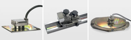
Workpiece Measurement
- Measuring Systems for Machine Tool Inspection and
Acceptance Testing
Machine tool performance from the point of view of compliances to tolerances, surface definition, etc., is determined essentially by the dynamic and static accuracy of machine movement. For precision machining it is therefore important to measure and compensate motional deviations. Guidelines and standards for inspecting machine tools (ISO 230-2, ISO 230-3 and ISO 230-4, and VDI/DGQ Directive 3441) stipulate a number of measuring methods for determining dynamic and static deviations.
Conventional inspection and acceptance testing of machine tools has been limited essentially to static measurement of the geometrical machine structure without load and on controlled machines to measuring positioning accuracy. Since the results of machining depend increasingly on dynamic deviations from the nominal contour and on high accelaration in the machine tool, the finished parts are also inspected for dimensional accuracy in order to draw conclusions about the dynamic behavior of the machine. The HEIDENHAIN measuring systems KGM and VM 182 can now be used to directly measure both dynamic and static components of deviation. The advantage of this direct inspection method over inspecting only the results of the machining lies in its separation of technological influences from machine influences, and in its capability of distinguishing individual factors of influence.
Dynamic measurements - especially at high traversing speeds -provides information on contouring behavior that permit conclusions about both the condition of the machine tool as well as the parameter settings of the control loop consisting of the CNC control, drives, and position feedback systems.
Static measurements - such as the measurement of position deviations in the linear axes using a comparator system - permit conclusions exclusively about the geometric accuracy of the machine.
Machine tool builders use the results of machine accuracy inspection for the purpose of making design improvements to increase accuracy. Such measurements also help them to optimize the commissioning parameters of the control loop wherever they influence the accuracy of a CNC machine.
Machine tool users can use these measuring systems for acceptance testing and regular inspection of their machine tools.
Measured Value Acquisition and Display
- Position Display Units
Position display units serve to visualize the values measured with linear encoders, length gauges, rotary encoders or angle encoders. Areas of application include:- Measuring and inspection equipment
- Dividing apparatuses
- Monitoring of measuring equipment
- Manual machine tools
- Measuring machines
- Highly readable, alphanumeric display
- Simple, logically arranged keypad
- Ergonomically designed push-button keys
- Splash-protected front panel
- Sturdy die-cast housing
Interface Electronics
Interface electronics from HEIDENHAIN adapt the encoder signals to the interface of the subsequent electronics. 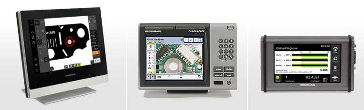
Position Display Units
- Position display units serve to visualize the values
measured with linear encoders, length gauges, rotary encoders or angle
encoders.
Areas of application include:- Measuring and inspection equipment
- Dividing apparatuses
- Monitoring of measuring equipment
- Manual machine tools
- Measuring machines
- Highly readable, alphanumeric display
- Simple, logically arranged keypad
- Ergonomically designed push-button keys
- Splash-protected front panel
- Sturdy die-cast housing
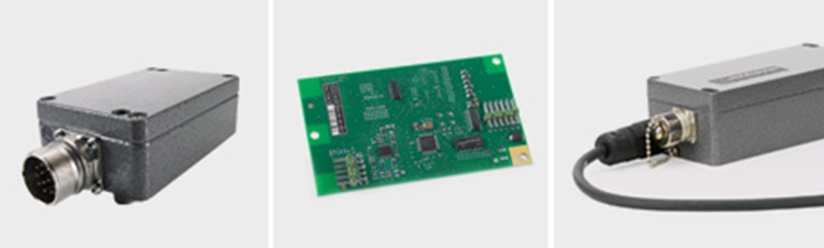
Interface Electronics
- The interface electronics from HEIDENHAIN adapt the
encoder signals to the interface of the subsequent electronics. They are
used when the subsequent electronics cannot directly process the output
signals from HEIDENHAIN encoders, or if additional interpolation of the
signals is necessary.
Input signals of the interface electronics
Interface electronics from HEIDENHAIN can be connected to incremental encoders with sinusoidal signals of 1 VPP (voltage signals) or 11 µAPP (current signals). The IK 220 PC expansion board can also process EnDat and SSI.
Output signals of the interface electronics
Interface electronics with the following interfaces to the subsequent electronics are available:- TTL square-wave pulse trains
- EnDat 2.2
- Fanuc Serial Interface
- Mitsubishi High Speed Serial Interface
- PCI-Bus
In addition to being converted, the sinusoidal encoder signals are also interpolated in the interface electronics. This results in finer measuring steps, leading to an increased positioning accuracy and higher control quality.
Formation of a position value
Some interface electronics have an integrated counting function. Starting from the last reference point set, an absolute position value is formed when the reference mark is traversed, and is output to the subsequent electronics.