- Offer Profile
- Lambert Instruments is
dedicated to development, production and worldwide sales of products for
imaging at low light levels.
Our procedure:- Analyze your problem
- Propose possible solutions and options
- Discuss the difference in price and performance.
- Create the most effective solution
- Based on the final specification the order is executed against the agreed price and delivery time.
Fluorescence Imaging

Fluorescence Lifetime Imaging Microscopy (FLIM) Systems
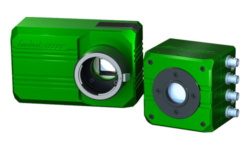
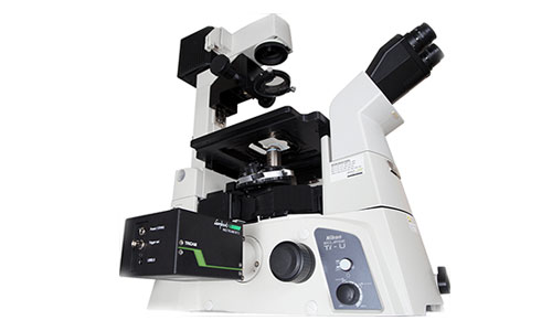
LIFA
-
Fluorescence lifetime imaging has never been easier
With the Lambert Instruments FLIM Attachment (LIFA), you record quantitative lifetime data in a matter of seconds. It's easy to connect our FLIM camera and light source to your microscope. And our specialized software records the images, analyzes the data instantly and presents the results visually for easy interpretation.
Features
IT'S FAST
Record fluorescence lifetime imaging microscopy (FLIM) data in a matter of seconds. Compared to alternative methods like time-correlated single photon counting (TCSPC), the LIFA is over 100 times faster.
IT'S EASY
Our advanced software instantly analyzes your data and presents the calculated fluorescence lifetimes visually. Recorded images are compatible with ImageJ, FIJI, Matlab and MetaMorph. Detailed statistical data can be exported to Excel worksheets.
IT'S COMPATIBLE
The LIFA is compatible with every fluorescence microscope with a camera output. This includes fluorescence microscopes by Leica, Nikon, Olympus, TILL and Zeiss, as well as confocal microscopes and TIRF microscopes.
OTHER FEATURES
Non-phototoxic illumination
High quantum efficiency with the optional Gen III GaAs intensifier
Time-lapse recording mode
Forster Resonance Energy Transfer (FRET) efficiency mapping
Multi-frequency acquisition for separation of multiple lifetimes
Polar (Phasor) plot inspection and separation of multiple lifetimes
Easy integration into specialized image analysis pipelines
COMPATIBILITY
The LIFA is compatible with several types of microscopes:
Widefield fluorescence microscopes
Confocal spinning disk fluorescence microscopes
Total Internal Reflection Fluorescence (TIRF) microscopes
Hyperspectral imaging system by Gooch & Housego
Prior filter wheels and XY stage for multi-channel acquisition
Applications
Oxygen Concentration
Successive lifetime fields in axial position x. Quantitative visualization of the increasing boundary layer thickness along downstream flow (45 μl/min). The flow direction is from left to right. The color bar refers to the lifetime, which is given in nanoseconds. The dashed arrows indicate the axial positions at which the local oxygen concentration profiles across the microchannel height are obtained.
Synapse-specific interactions in live neurons
At the university of Bordeaux Segalen, the molecular mechanisms underlying memory storage in the brain are being unraveled by studying protein accumulation at synapses. With the LIFA attached to a confocal spinning disk microscope, lifetime imaging of synapse-specific interactions in live neurons allowed the researchers to show and quantify the synapse specific interaction of the two proteins of interest.
Oil Characterization
Fluorescence imaging can be used to obtain a chemical signature of oil. All kinds of oil, from edible to motor oil, are distinguishable using fluorescence analysis. For more information, please refer to our application note on time-resolved fluorescence in the analysis of edible oils.
Models
LIFA
Fluorescence lifetime imaging
Lifetime range: 1 - 300 ns
Modulation frequencies: 1 - 120 MHz
LIFA-P
Phosphorescence lifetime imaging
Lifetime range: 300 ns - 1 ms
Modulation frequencies: 0 - 100 kHz
LIFA-X
Fluorescence and phosphorescence lifetime imaging
Lifetime range: 1 ns - 1 ms
Modulation frequencies: 0 kHz - 120 MHz
Specifications
CAMERA SPECIFICATIONS- Pixel resolution: 1392 x 1040 pixels
- Spatial resolution (min.): 19 to 26* lp/mm
- Dynamic range: 12 bit
- Effective pixel size: 10.3 μm
- Equivalent background input: 0.25 μlx
* 19 lp/mm for GaAs and GaAsP photocathodes. 26 lp/mm for S20 and S25 photocathodes.
LIFETIME SPECIFICATIONS- Lifetime resolution: < 100 ps
- Lifetime range: 0.1 ns - 1 ms
- Framerate (max.): 2 lifetime images per second
COMPONENTS
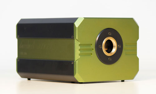
The LIFA system consists of three main components:- LIFA: the signal generator that synchronizes the light source and the camera
- TRiCAM: an intensified CCD camera that records the lifetime images
- Light source: high-stability modulated Multi-LED or Multi-LASER
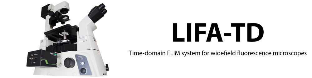
LIFA-TD
-
Time-domain FLIM system for widefield fluorescence microscopes
The LIFA-TD offers a turn-key solution for fluorescence lifetime imaging microscopy and is compatible with every widefield fluorescence microscope. From recording the data to calculating the fluorescence lifetime, the entire measurement procedure is automated by our advanced software.
Features
EASY
Our advanced software automatically records the required images and does all the necessary fluorescence lifetime calculations for you.
COMPATIBLE
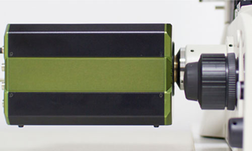
The LIFA-TD works with every widefield fluorescence miscroscope. The LIFA Camera is very easy to install on the camera port of your microscope.
AFFORDABLE
The standard configuration of the LIFA-TD offers an entry-level set-up for FLIM measurements.
Specifications
SYSTEM SPECIFICATIONS- Non-phototoxic illumination
- High quantum efficiency with the optional Gen III GaAs image intensifier
- Time-lapse recording mode
- Easy integration into specialized image analysis pipelines
CAMERA SPECIFICATIONS- Pixel resolution: 1392 x 1040 pixels
- Spatial resolution (min.): 19 to 26* lp/mm
- Dynamic range: 12 bit
- Effective pixel size: 10.3 μm
- Equivalent background input: 0.25 μlx
* 19 lp/mm for GaAs and GaAsP photocathodes. 26 lp/mm for S20 and S25 photocathodes.
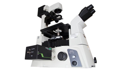
Fluorescence Imaging
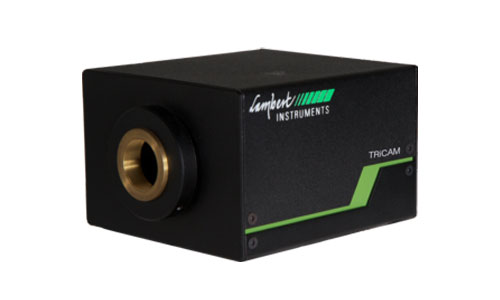
TRICAM
-
Intensified Camera with Ultra-Short Gating
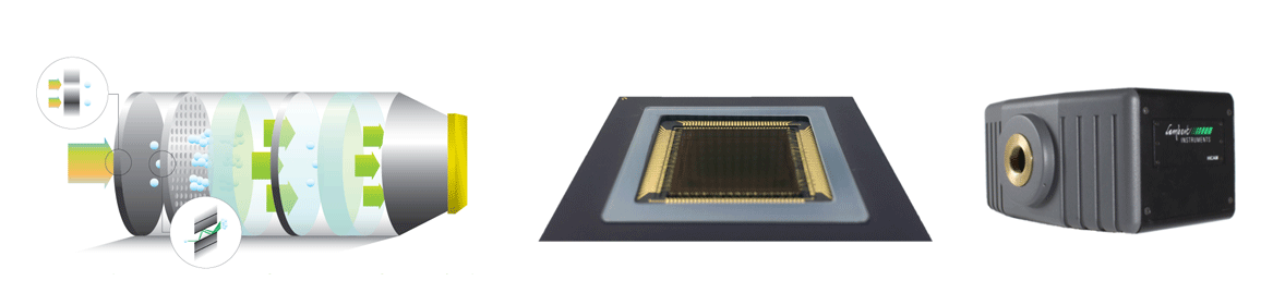
The TRiCAM is a compact intensified camera. It is designed for scientific and industrial applications that require low-light imaging. With built-in signal generators, the TRiCAM is capable of ultra-short exposures through fast gating and frequency-domain imaging using lock-in detection.
ModelsTRiCAM G
GATED IMAGE INTENSIFIER
The TRiCAM G is equipped with an integrated timing pulse generator and a gate-unit. The integrated gate unit generates gate pulses down to < 3 ns.
TRiCAM M
MODULATED IMAGE INTENSIFIER
Modulation at up to 120 MHz is provided by a single-chip digital synthesizer to ensure very low phase noise.TRiCAM GM
GATED AND MODULATED INTENSIFIER
This is a combination of the gated and modulated versions of the TRiCAM. This versatile camera is capable of both gated and modulated imaging.
ApplicationsThe TRiCAM is a versatile imaging system that can be used for a wide variety of applications. These are some of the applications that our customers use the TRiCAM for:
Time-resolved fluorescence in the analysis of edible oilsFluorescence spectroscopy is an effective method to obtain a physical or chemical signature for delineating the composition and characteristics of organic matter. It is a major tool for analyzing food security. However, since most organic ingredients have similar fluorescent spectra, it is difficult to distinguish them with high precision by traditional fluorescence analysis.
Diffuse Optical Tomography
The TRiCAM is a gain-modulated intensified CCD camera for Near-Infrared Diffuse Optical Tomography. It allows scientific-grade imaging of tissue properties for 3D reconstruction of chromophore concentrations in biomedical optics. Its well-established frequency-domain technology allows fast acquisition of macroscopic images at high accuracy. The TRiCAM comes with a dual signal generator and power supply and optional software for extracting the phase shift and demodulation information. Lambert Instruments also offers high modulation depth laser diodes that can be modulated across a broad frequency range for optimal sensitivity.
The Lambert Instruments TRiCAM is easy to operate and has been used in optical breast cancer screening and brain imaging.
TRICAM KEY FEATURES- Highly sensitive and fast diffuse optical tomography acquisition
- Higher quantum efficiency with the optional Gen III GaAs intensifier
- Easy integration into biomedical imaging systems
Intensity-based FRETIn the intensity-based Forster Resonance Energy Transfer (FRET) method, change in emission intensities from donor and acceptor fluorophores is measured. During FRET, the amount of emitted photons (emission intensity) from the donor fluorophore decreases and the emission intensity from the acceptor fluorophore increases. The FRET efficiency is basically calculated from the ratio of emission intensities from donor and acceptor before and after FRET occurrence.
To obtain accurate FRET data by sensitized emission, three images have to be acquired:
1. Donor excitation with donor emission,
2. Donor excitation with acceptor emission,
3. Acceptor excitation with acceptor emission.The major advantage of this method over fluorescence lifetime imaging microscopy (FLIM)—which is a donor-based FRET detection—is that it can be carried out with standard wide-field or confocal fluorescence microscopes that are available in most laboratories. Moreover, it yields additional data on the acceptor population. However, quantitative sensitized emission requires significant attention for corrections and calibration, whereas FLIM-based FRET techniques are inherently quantitative from first physical principles.
Image Intensifier
Low-Light Imaging
The TRiCAM has a built-in image intensifier that boosts the incoming light. This way, you can capture detailed images in the most challenging light conditions.
Our experienced engineers will help you pick the right image intensifier for your application.
Fiber-Optically Coupled
Our experienced engineers couple the sensor to the image intensifier with a fiber-optic window. This is a solid piece of glass that consists of millions of parallel glass fibers sealed together. Each fiber acts as an independent light conductor that transfers the light from the image intensifier to the sensor.
ULTRA-SHORT GATING
The image intensifier in the TRiCAM can be used as an ultra-fast shutter by switching it on and off again very quickly. This technique is called gating and it can be done in a matter of nanoseconds.
Gating can eliminate motion blur when imaging fast-moving objects or highly dynamic processes. By varying the timing of the gate signal, you can use gating to record a time-resolved light intensity profile.
OPTIMIZED FOR YOUR APPLICATION
The TRiCAM can be configured with a wide range of image intensifiers. Available image intensifiers cover the entire visual spectrum and the near infrared.
Our experienced engineers will help you pick the right image intensifier for your application.
High-Resolution Sensor- 2.3 Megapixels
- 160 fps
- Global Shutter
Specifications
IMAGE INTENSIFIER- Diameter: 18mm
- Minimum Gate Width: 40ns (<3 ns optional)
- Maximum Repetition Frequency: 300 kHz
- Trigger Input: TTL
SENSOR- Resolution: 1920 x 1200 pixels
- Pixel Size: 5.86 µm
- Frame Rate: 162 fps
- Sensor Type: CMOS
- Readout Method: Global Shutter
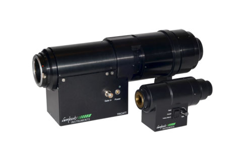
- ADC: 10 bit and 12 bit

TRICATT
-
Compact Lens-Coupled Image Intensifier
The TRiCATT is a compact lens-coupled image intensifier for scientific and industrial applications that require- Low-light level imaging
- Ultra-short exposures through fast gating
- Frequency-domain imaging using lock-in detection
Any camera with C-mount and a 1/2", 2/3", or 1" image sensor is compatible with the TRiCATT.
Features
High resolution image intensifiers
Gen II and Gen III image intensifiers offering the world’s highest resolution and sensitivity in the UV, visible or near infrared.
Small gate widths
Gate width down to less than 3 ns (FWHM) with minimal jitter.
High gate repetition rates
Up to 300 kHz / 2.5 MHz burst.
Compact design
For an easy fit to your imaging or spectroscopy setup.
Overexposure protection
User-definable current limitation and optional shutter.
Easy coupling
Efficient lens coupling to any CCD and CMOS camera (up to 500 fps) with C-mount input and output.
Automatic Day/Night Operation
The TRiCATT G can be supplied with automatic gain and gating control enabling 24 hours day/night operation.
Relay Lens
The high quality relay lens transfers the intensified image to the image sensor of the attached camera very efficiently and without losses in resolution. If required we can provide the 0.5x relay lens with a back focal distance of 13 mm.
Camera
Along with the Image Intensifier TRiCATT Lambert Instruments can deliver different types of CCD and CMOS cameras.
Applications- Time-resolved imaging and spectroscopy
- Particle Image Velocimetry (PIV)
- Laser Induced Fluorescence (LIF)
- Diffuse Optical Tomography (DOT)
- Time-gated luminescence
- Fluorescence Lifetime-Imaging Microscopy (FLIM)
- Forster Resonance Energy Transfer (FRET)
- Oxygen imaging
- Viscosity imaging
- Single-molecule imaging
- Bio- and chemiluminescence imaging
- Solar PV and LED characterization
- Combustion research
- Time-gated Raman
- Plasma physics
- X-ray Imaging
ModelsTRiCATT M
MODULATED IMAGE INTENSIFIER ATTACHMENT
The TRiCATT M is the successor of the II18MD modulated image intensifier and is a key component in camera based/frequency-domain systems for low-light-level applications.
TRiCATT G
GATED IMAGE INTENSIFIER ATTACHMENT
The TRiCATT G increases the sensitivity of the camera and enables the detection of images at a light levels as low as 0.01 mlux.
Control units
The control unit contains a micro-controller, a high voltage power supply and a RF (Radio Frequency) amplifier. The control unit has a low voltage input to receive the external modulation signal. It amplifies this signal and biases it with a variable DC photocathode voltage. The control unit offers control of the MCP voltage for setting the image intensifier gain. The control unit also monitors the light output, and switches off the image intensifier when its light output becomes too high. The control unit supports modulation frequencies up to 120 MHz.
MANUAL GAIN CONTROL
Gain control (manual)
GAIN CONTROL
Gain control
Anode current limiter
Shutter control (optional)
GATE CONTROL
Gain control
Gate control
GATE GENERATOR
Gain control
Gate control
Anode current limiter
Internal trigger generator
Shutter control
Programmable gate (optional)
OptionsOptional: Signal Generator
Instead of using an external modulation signal generator, we offer a built-in modulation signal generator as part of the control unit/power supply for frequencies up to 120 MHz.
Optional: TRiCAM
As an alternative to the lens-coupled ICCD camera (TRiCATT + CCD), we offer an ICCD camera in which the image intensifier is fiber-optically coupled to the sensor. This is the TRiCAM. This modulated intensified CCD camera is very compact and has a significantly higher gain than the lens-coupled combination as a result of the more efficient and compact fiber coupling.
SpecificationsGating Specifications
STANDARD GATING FAST GATING Width range 40 ns - 10 s <3 ns - 10 s Resulting min. pulse width 40 ns (20ns) <3 ns (10 ps) Pulse repetition rate <10 MHz <16 MHz Delay jitter (width) ± 10 ns (± 250 ps) <35 ps (<35 ps) Insertion delay 100 ns 20 ns
Modulated Light Sources
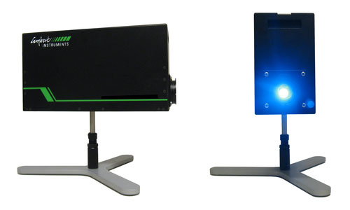
Multi-LED
-
Versatile pulsed excitation light source for FLIM
The Lambert Instruments Multi-LED is a versatile pulsed excitation light source for fluorescence lifetime imaging microscopy in the frequency domain. The Multi-LED contains up to 4 LEDs that provide non-phototoxic illumination levels, have a low cost and a long economic lifespan.
Available wavelengths cover the range from 360 to 640 nm. The Multi-LED is part of the Lambert LIFA and LIFA-X products for fluorescence lifetime imaging microscopy/Forster Resonance Energy Transfer (FRET), and is seamlessly integrated with the LI-FLIM software. For each LED automatic control is available for LED selection, LED current and modulation frequency.
APPLICATIONS- Molecular interactions
- Protein conformation
- Biosensors
- Oxygen concentration imaging in cells and tissue
- NADH / FAD fluorescence dynamics
- Viscosity imaging
- Membrane dynamics
- Membrane trafficking
- LED inspection
- Crude oil characterization
FEATURES- Lifetime accuracy as part of the LIFA system less than 30 ps
- Fast switching between individual LEDs, no realignment of the lightsource or other manual interventions needed.
- Digital modulation up to 80-120 MHz, depending on the wavelength
- Choice between lens-coupling and fiber-coupling to your microscope
- Integrated USB 2.0 control
- Compatible with all major microscope brands
- Dimensions (l x w x h): 346 x 109 x 183 mm
AVAILABLE WAVELENGTHS
All LEDs are high-quality modulating LEDs with a peak light intensity at wavelengths between 446 and 525 nm, 595 nm, 635 nm and 696 nm. Other wavelengths are available upon request.
TEMPERATURE STABILIZATION
Increased temperature stabilization of the LED's is optionally available to minimize lifetime drifts during very long (many hours) time lapses.
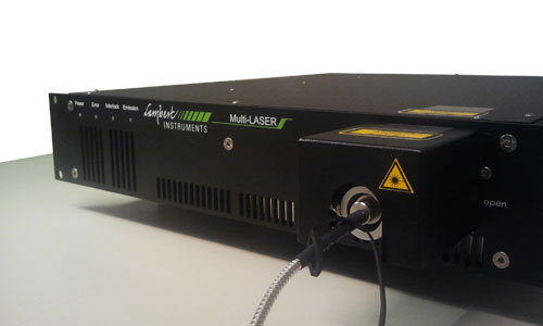
Multi-LASER
-
Light Source for Frequency-Domain FLIM
The Multi-LASER is a light source for frequency-domain fluorescence lifetime imaging microscopy. The Multi-LASER contains up to 6 laser diodes with different wavelengths.
The Multi-LASER modulated diodes offer the high stability and high modulation depth required for lifetime imaging, and can also be used for regular fluorescence imaging. Using the Kineflex coupling system the light source can be easily coupled into your microscope stand for multi-beam confocal illumination, TIRF illumination, and widefield illumination. The Multi-LASER is part of our LIFA product line for fluorescence lifetime imaging microscopy. For each laser line the laser power and modulation characteristics can be set from the LIFA software LI-FLIM.
APPLICATIONS- Fluorescence imaging
- Flow cytometry
- LED inspection
- Crude oil characterization
- Machine Vision
MODELS
Two models of the Multi-LASER are available: a standard version including up to 6 lines with a 50 ps lifetime repeatability for 0-4 ns lifetimes, and an extreme version with a ultra-high modulation depth including up to 4 lines with a 20-30 ps lifetime repeatability in the same lifetime range.
FEATURES- Choice of 1-6 laser diodes
- Choice of 20 different wavelengths between 375 nm and 830 nm
- Single-mode optical output powers up to 250 mW
- LIFA lifetime accuracy less than 50 ps (standard) or less than 20-30 ps (extreme)
- High-speed digital modulation up to 180 MHz, modulation depth > 250:1 (standard) and > 2500000:1 (extreme)
- Power stability: better than 2% (standard), better than 0.5% (extreme)
- Kineflex fiber coupling system and (optional) single-mode fiber
- 19" rack type housing, dimensions up to (l x w x h): 530 mm x 484 mm x 132 mm, depening on the number of laser diodes
High-Speed Imaging
High-Speed Cameras
Lambert HS540
-
High Speed, High Resolution, High Performance
The Lambert HS540M and the Lambert HS540S offer simple and efficient high-speed imaging for scientific research, R&D, machine vision and other industrial applications.
LAMBERT HS540M
The Lambert HS540M is a high-speed camera for research applications. It has up to 16 GB of internal storage and is ideal for scientific research and industrial R&D. After recording your data, you can review the results in our software and trim the high-speed video before exporting it to your computer.
LAMBERT HS540S
The Lambert HS540S is a streaming high-speed camera for industrial applications. It is designed for high-performance tasks like machine vision, quality control and wafer inspection. Instead of saving the images to internal storage, the camera streams high-speed video directly to your computer over a CoaXPress (CXP) interface.
Sensor540 fps
The Lambert HS540 cameras record full-resolution images at 540 fps. To increase the framerate, the cameras can use a smaller part of the sensor to reduce the image resolution. By doing so, they can operate at up to 166 000 frames per second.
1696 x 1710 pixels
The sensor in the Lambert HS540 cameras has a full resolution of 1696 x 1710 pixels. You can change the resolution settings in the software to increase the maximum framerate or to increase the maximum recording duration.
Global Shutter
The sensor in the Lambert HS540 Series cameras uses an electronic global shutter. This ensures that all pixels are read out at the same time to prevent rolling shutter effects. Its minimum exposure time of 2 us ensures sharp images of fast-moving objects.
High Speed, High Standards
To transfer all the high-resolution image data, the Lambert HS540S streams live over a CoaXPress (CXP) interface. The camera has four CXP connectors, each of which has a channel speed of 5 Gbit/s. With Power over CXP (PoCXP) the camera can be powered over the CoaXPress channels, removing the need for a dedicated power cable.
Specifications
SENSOR SPECIFICATIONSResolution 1696 x 1710 pixels, 8 bit color or monochrome Framerate 540 fps (full resolution) 5000 fps (480 x 480 px) Shutter Global Shutter CMOS Pixel size 8 um square A/D Converter 8 bit Dynamic Range 49 dB (EMVA1288) Signal-to-Noise Ratio 42 dB (EMVA1288) INPUT AND OUTPUT
Trigger Modes Internal free-run, external, CXP External Trigger TTL signal, 3.3-5 V, 10 mA, optically isolated Software Trigger Programmable exposure (timed of width) Lens Mount F-mount, C-mount, M42-mount, custom Power Power over CoaXPress, 24 VDC/12 W CXP Connector BNC CXP Channel Speed 5.00 Gbit/s, CXP-5 ENVIRONMENTAL PARAMETERS
Environmental 0°C to +40°C Humidity < 80% relative, non-condensed
Intensified High-Speed Cameras
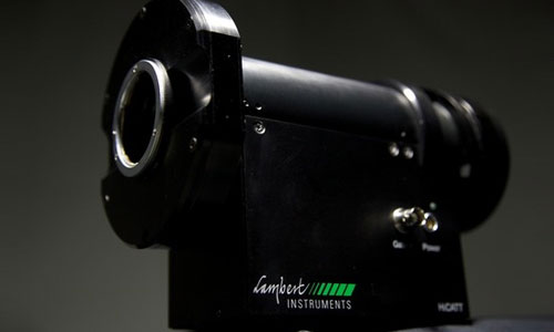
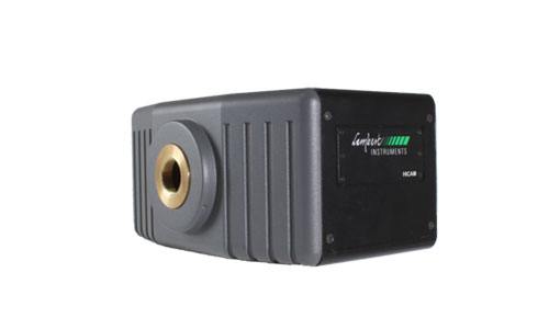
HiCAM
-
Gated Intensified High-Speed Camera
The HiCAM is a gated intensified high-speed camera. It has an integrated fiber-optically coupled image intensifier, which offers a unique combination of high speed and sensitivity down to single photon level. Because the HiCAM does not need high intensity light sources, it is suitable for use in low-light level conditions. The HiCAM can record up to 200,000 frames per second.
The dual-stage image intensifier, specially designed for high-speed cameras, can be equipped with a variety of photocathodes; ranging from ultra violet to infra red. Adapting the photocathode will give maximum output brightness to enhance Signal to Noise Ratio (SNR). Moreover, the image intensifier is fiber-optically coupled to a CMOS sensor. This further increases SNR, as compared to a lens-coupled system. The HiCAM is available in 2 versions, the very sensitive HiCAM 500 and the ultra fast HiCAM 5000.
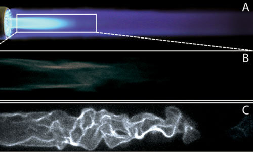
ApplicationsGAS FLAME
Blue gas flames (mix Butane - Propane) with added sparkles recorded at 1000 fps (frame rate) and gating of 15 us (effective exposure time). Resolution: 1280 x 512 pixels.
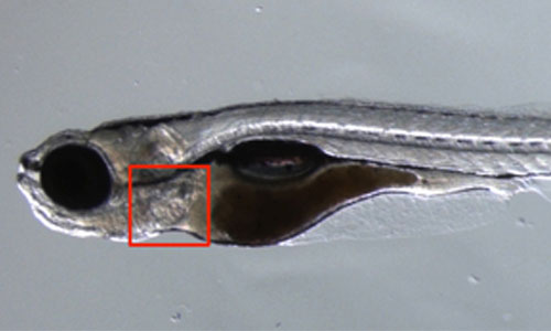
BEATING ZEBRAFISH HEART
Recording of a beating zebrafish heart at 2000 frames per second with the Lambert Instruments HiCAM on a fluorescence microscope. The blood cells were stained with a DS-red fluorophore.
CORK BURNING IN PLASMA
High-speed recording of a cork burning in plasma. Recorded with a HiCAM at 5000 fps.
OTHER APPLICATIONS- Super-slow motion combustion research for the automotive industry
- Time-resolved imaging in plasma physics research
- Dynamic phenomena in microscopy, e.g. Imaging the rotation of single molecules of ATPase
- Laser-Induced Fluorescence (LIF)
- Flow visualization and velocity measurements using Particle Image Velocimetry (PIV)
- Time-resolved imaging of fluids for microfluidic research
- Blood flow analysis
- Time-resolved fluorescence
Specifications
HICAM 500M/S HICAM 540M/S HICAM 1000M/S Framerate (Full Resolution) 500 fps 540 fps 1000 fps Sensor Resolution 1280 x 1024 pixels 1696 x 1710 pixels 1280 x 1024 pixels Internal Memory HiCAM 500M: 8 or 16 GB HiCAM 540M: 8 or 16 GB HiCAM 1000M: 16 GB Streaming HiCAM 500S HiCAM 540S HiCAM 1000S Bit Depth 8 and 10 bit 8 bit 8 and 12 bit

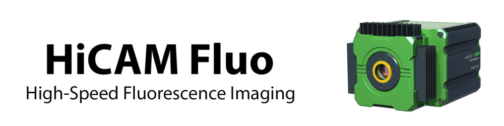
HiCAM Fluo
-
High-Speed Fluorescence Imaging
The HiCAM Fluo is a high-speed camera for fluorescence applications. It records high resolution images at a framerate of 540 fps in the most challenging low-light conditions by using a cooled image intensifier. Packed into a compact aluminum enclosure, it is easy to attach the HiCAM Fluo to any fluorescence microscope.
Applications
Applications of the HiCAM Fluo include:- High-speed fluorescence, bioluminescence and chemiluminescence detection for in-vivo imaging
- Time-resolved imaging of fluids for microfluidic research
- Flow visualization and velocity measurements using Particle Image Velocimetry (PIV)
- Time-resolved imaging and spectroscopy using ultra-short exposures
- Laser-Induced Fluorescence (LIF)
- Super-slow motion combustion research for the automotive industry
- Time-resolved imaging in plasma physics research
- Single-photon imaging for astronomy
Recording of a beating zebrafish heart at 2000 frames per second with the Lambert Instruments HiCAM on a fluorescence microscope. The blood cells were stained with a DS-red fluorophore.
Features
FIBER-OPTICALLY COUPLED INTENSIFIER
The HiCAM is a gated intensified high-speed camera. It has an integrated fiber-optically coupled image intensifier, which offers a unique combination of high speed imaging and increased light sensitivity down to single photon level. Because the HiCAM does not need high-intensity light sources, it is suitable for use in low-light level conditions like fluorescence imaging.
COAXPRESS
To transfer all the high-resolution image data, the HiCAM Fluo streams live over a CoaXPress (CXP) interface. The camera has four CXP connectors, each of which has a channel speed of 5 Gbit/s. With Power over CXP (PoCXP) the camera can be powered over the CoaXPress channels, removing the need for a dedicated power cable.
ULTRA-SHORT GATING
With its gated image intensifier, the camera's effective exposure time can be reduced. The minimum gate width of 10 ns (FWHM) increases the range of light levels at which the camera can be used. It also eliminates motion blur and enables time-resolved filtering.
COOLED IMAGE INTENSIFIER
The fanless design of the camera minimizes vibrations to ensure sharp images. Very low noise levels are achieved by Peltier cooling the image intensifier. Noise levels are reduced by a factor of up to 100 times as compared to uncooled intensified cameras.
Sensor
540 fps
The HiCAM Fluo records full-resolution images at 540 fps. To increase the framerate, the camera can use a smaller part of the sensor to reduce the image resolution. By doing so, it can operate at up to 170000 frames per second.
1696 x 1710 pixels
The sensor in the HiCAM Fluo has a full resolution of 1696 x 1710 pixels. You can change the resolution settings in the software to increase the maximum framerate or to increase the maximum recording duration.
Global Shutter
The sensor in the HiCAM Fluo uses an electronic global shutter. This ensures that all pixels are read out at the same time to prevent rolling shutter effects. In combination with intensifier gating, exposure time can be reduced to 40 ns.
SpecificationsMaximum resolution 1710 x 1696 pixels Framerate 540 fps at full resolution 1000 fps at 1200 x 1200 pixels 5000 fps at 480 x 480 pixels Minimum exposure time 40 ns Gating repetition rate 100 kHz Image intensifier Proximity-focused image intensifier Photon gain (max.) 36000 lm/m^2/lx Computer interface Streaming CoaXPress
Intensified High-Speed Camera Attachments
HiCATT
-
High-Speed Intensified Camera Attachment
The High-speed Intensified Camera Attachment (HiCATT) is designed for use with a high-speed camera. The HiCATT increases the sensitivity of a high-speed camera and allows low-light-level imaging applications at framerates up to 200000 fps. The HiCATT F-mount and C-mount connections offer optimal flexibility and are available in both 18 mm and 25 mm input diameter.
The technology in the HiCATT expands the dynamic range of a high-speed camera. At low light-level input, even single photons can be detected. While at high light levels, overexposure is prevented by the use of very short gate pulses (down less than 3 ns), reducing the duty cycle of the image intensifier by a factor of up to 10000 times. Moreover, these short exposures yield sharp images of fast moving objects.
Features
300 000 fps
HIGH-SPEED IMAGING
The HiCATT upgrades your high-speed camera to the next level of performance. Itboosts the intensity of incoming light at speeds up to 300 000 fps.
3 ns
ULTRA-SHORT EXPOSURES
The gated image intensifier enables exposure times down to 3 ns. At such short exposure times, motion blur is eliminated completely to ensure sharp images.
50% QE
HIGH-SENSITIVITY INTENSIFIERS
You can choose from a wide variety of high-sensitivity image intensifiers to match the spectral needs of your application.
OPTIMIZED FOR YOUR APPLICATIONThe HiCATT can be configured with a wide range of image intensifiers. Our experienced engineers will help you pick the right image intensifier for your application.
COMPATIBLE WITH YOUR CAMERA
With standard C-mount or F-mount input and output, the HiCATT is compatible with any high-speed camera.
ApplicationsBUTANE-PROPANE FLAME AT 4200 FPS
Flames (mix Butane - Propane) at 4200 fps and 40 us gate open time (effective exposure time), HiCATT 25 image intensifier, high-speed camera attachment with Phantom V4.0 high-speed camera.
ELECTRONIC DISCHARGE AT 47000 FPS
Electronic Discharge at 47000 fps and 3 us gate open time (effective exposure time), HiCATT 25 image intensifier, high-speed camera attachment with Phantom V7.1 high-speed camera.
GAS COMBUSTION AT 5000 FPS
Gas combustion observed at 5,000 fps with HICATT High Speed Image Intensifier, Gen 2, 10µs exposure time. Fore more info go to www.axiomoptics.com. The HICATT High Speed Intensifier used for this video was coupled to a NAC Memrecam camera. It is also compatible with pco.Dimax, Phantom, Photron Fastcam or Optronis cameras.
COMBUSTION RESEARCH
Researchers around the world are using the HiCATT in their combustion studies involving OH* laser-induced fluorescence (LIF) and chemiluminescence. To avoid motion blur and to see the detailed structures, a very short exposure time is required. This reduces the light intensity that is detected during each exposure. The HiCATT boosts the light intensity to ensure clear images at high frame rates.
Other applications- Super-slow motion combustion research for the automotive industry
- Time-resolved imaging in plasma physics research
- Dynamic phenomena in microscopy
- Laser-Induced Fluorescence (LIF)
- Time-resolved imaging of fluids for microfluidic research
- Fluorescence Recovery After Photobleaching (FRAP)
- Many other industrial or scientific low-light-level applications in high-speed imaging
Control Units
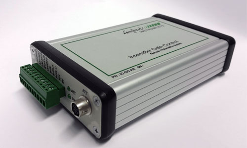
INTENSIFIER CONTROL
-
Intensifier Control for Automated Systems
For integration into a larger system or for automated measurements, the gain control unit for automated systems lets you control the settings of the intensifier attachment. The control unit uses standard TTL and analog signals for communication, allowing the user to switch the intensifier on or off, alter the gain and the anode current limit of the image intensifier without the need of software integration.
IMAGE INTENSIFIER GAIN
By increasing the image intensifier gain, the incoming light intensity will be boosted more, resulting in a brighter image. The intensifier control for automated systems lets you control the gain of the image intensifier.
ANODE CURRENT LIMIT
To protect the fragile image intensifier from being damaged by overexposure, the anode current limiter can be used to set a limit for the acceptable anode current. If the anode current exceeds this value, then the image intensifier will be switched to a safe mode.
COMPATIBILITY
The gain control unit for automated systems is compatible with our intensifier attachments:- HiCATT
- TRiCATT
Scientific Imaging
TRiCAM
-
Intensified Camera with Ultra-Short Gating
The TRiCAM is a compact intensified camera. It is designed for scientific and industrial applications that require low-light imaging. With built-in signal generators, the TRiCAM is capable of ultra-short exposures through fast gating and frequency-domain imaging using lock-in detection.Models
TRiCAM G
GATED IMAGE INTENSIFIER
The TRiCAM G is equipped with an integrated timing pulse generator and a gate-unit. The integrated gate unit generates gate pulses down to < 3 ns.
TRiCAM M
MODULATED IMAGE INTENSIFIER
Modulation at up to 120 MHz is provided by a single-chip digital synthesizer to ensure very low phase noise.
TRiCAM GM
GATED AND MODULATED INTENSIFIER
This is a combination of the gated and modulated versions of the TRiCAM. This versatile camera is capable of both gated and modulated imaging.
TRiCATT
-
Compact Lens-Coupled Image Intensifier
The TRiCATT is a compact lens-coupled image intensifier for scientific and industrial applications that require- Low-light level imaging
- Ultra-short exposures through fast gating
- Frequency-domain imaging using lock-in detection
Any camera with C-mount and a 1/2", 2/3", or 1" image sensor is compatible with the TRiCATT.
Features
High resolution image intensifiers
Gen II and Gen III image intensifiers offering the world’s highest resolution and sensitivity in the UV, visible or near infrared.Small gate widths
Gate width down to less than 3 ns (FWHM) with minimal jitter.High gate repetition rates
Up to 300 kHz / 2.5 MHz burst.Compact design
For an easy fit to your imaging or spectroscopy setup.Overexposure protection
User-definable current limitation and optional shutter.Easy coupling
Efficient lens coupling to any CCD and CMOS camera (up to 500 fps) with C-mount input and output.Automatic Day/Night Operation
The TRiCATT G can be supplied with automatic gain and gating control enabling 24 hours day/night operation.Relay Lens
The high quality relay lens transfers the intensified image to the image sensor of the attached camera very efficiently and without losses in resolution. If required we can provide the 0.5x relay lens with a back focal distance of 13 mm.Camera
Along with the Image Intensifier TRiCATT Lambert Instruments can deliver different types of CCD and CMOS cameras. If you already have a camera, you can use our interactive calculator to determine which intensifier size and relay optics are best suited for your setup.

Intensified Spectroscopy
-
Spectroscopy on a Nanosecond Timescale
Intensified spectroscopy involves acompact spectrometer, such as the AvaBenchOptical Bench by Avantes, coupled to an intensified CCD or CMOS camera.
A compact spectrometer, such as the AvaBenchOptical Bench by Avantes, is coupled to an intensified CCD or CMOS camera. The input of the intensifier matches the size and spectral range of the projected spectrum. The output is fiber coupled to the CCD or CMOS image sensor. The image intensifier with nanosecond gating provides spectroscopy on a nanosecond timescale. The combination with the intensified high speed CMOS camera allows a recording rate of tens of thousands spectra per second.
APPLICATIONS- Combustion research
- Monitoring dynamic processes
- Raman spectroscopy
- Food sorting
- Air pollution detection
FEATURES- Single photon sensitivity
- Spectral range from UV to NIR
- Spectral resolution down to 0.5 nm
- Variable exposure time down to 3 ns
- Recording up to 100000 spectra/s
Custom Solutions
-
Lambert Instruments specializes in high-end imaging solutions and is known for producing Custom Imaging Products. Custom imaging products for low light level applications can be made according to customer specifications.
Imaging products for low light level applications, can be made according to customer specifications, such as: special multi-stage intensifiers, cooled intensifiers, intensified high speed cameras, intensified CCD cameras, image sensor with fiber optic input window.
Image Intensifiers
Lambert Instruments has over twenty years of experience with image intensifiers. Our engineers are experts in choosing the right image intensifier for your imaging application. Our highly specialized customs products include- Cooled image intensifiers for ultra-low noise
- Specialized image intensifier configurations for corona imaging in high-voltage applications
- Multi-stage image intensifiers with multiple boosters
Sensors
Our standard product range offers only a part of the available types of camera sensors. But our custom solutions can include just about every type of sensor you can think of. We have experience with- Line-scan sensors
- Fiber-coupled scintillators
- Fiber-coupled line scan/TDI sensors
- Sensors with interchangeable fiber-optical window
Custom Software Solutions
Lambert Instruments offers custom software solutions for a wide variety of imaging standards, including- GigE Vision
- GenICam
- CoaXPress
- CameraLink
Applications
Fluorescence Lifetime Imaging with a Time-Domain FLIM System on a Widefield Microscope
-
Fluorescence lifetime can be recorded for every pixel in the image simultaneously with a time-domain FLIM camera. This method requires an intensified camera, a pulsed laser and a widefield fluorescence microscope. This is typically more cost-effective than alternative methods that need a confocal set-up.
One of the most popular methods for fluorescence lifetime imaging microscopy (FLIM) is time-correlated single photon counting (TCSPC). This method requires a confocal microscope with a pulsed laser and a photomultiplier tube (PMT). The sample is briefly illuminated by a laser pulse after which the PMT counts the number of emitted fluorescence photons.
Revealing Cancer's Infrastructure
- This year marks the 10th anniversary of the LIFA. With the first Lambert Instruments FLIM Attachment (LIFA) a decade ago, we introduced an easy and fast approach to fluorescence lifetime imaging. Since then, we advanced our imaging and analysis software; we improved our hardware and made it more compact; and we added compatibility with third-party hardware. But at the heart of the LIFA experience are still the features that matter most to our users. They are using the LIFA every day, because it is the easiest and fastest system for fluorescence lifetime imaging microscopy.
High-speed in vivo imaging of a zebrafish heart
- Recording images of living organisms at high frame rates with a fluorescence microscope is challenging. High-speed imaging requires a considerable light intensity, because at high frame rates the image sensor is exposed to light very briefly. During that short period of time, enough light needs to be captured to obtain a clear image. Normally, this is achieved by increasing the intensity of the illumination. Because the more light bounces off the object, the more light reaches the camera. But when studying fluorescence or chemiluminescence, the object itself emits light and increasing the intensity of the emitted light is often not possible. In such a situation, the solution is to increase the intensity of the light that is detected by the camera.
Time-resolved fluorescence in the analysis of edible oils
-
Fluorescence spectroscopy is an effective method to obtain a physical or chemical signature for delineating the composition and characteristics of organic matter. It is a major tool for analyzing food security. However, since most organic ingredients have similar fluorescent spectra, it is difficult to distinguish them with high precision by traditional fluorescence analysis.
PhD Mu, considering the time characters of the fluorescent spectra, develops a new method based on time-resolved fluorescence. The time resolution is 3 ns realized by a TRiCAM: a gated, intensified CCD camera by Lambert Instruments. The contour diagrams of the time-resolved fluorescence intensities (CDTRFIs) of different kinds of edible oils are acquired. Outperforming traditional fluorescence analysis, CDTRFIs greatly improve the identification capabilities without sacrificing the advantages of traditional fluorescence analysis.
Oxygen transport across slippery and curved gas-liquid interfaces using phosphorescence lifetime imaging
-
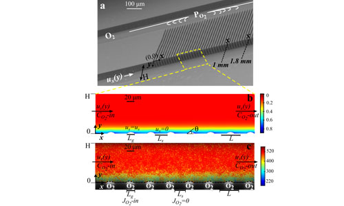
The transport phenomena at interfaces often determine or limit the overall performance of processes. Direct investigations of interfacial transport of momentum, mass and heat at the interfaces in micron scale are highly appreciable for further optimization of various micro and macroscale technologies. The Soft Matter Group at the University of Twente (The Netherlands), lead by Prof. Dr. Rob Lammertink, aims at gaining a better understanding of transport phenomena near boundaries, so that various processes such as desalination, separation of species and (photo)catalytic reactions can be improved.
Microfluidics offer an ideal platform allowing for the integration of 'controllable' surfaces and direct measurements of transport phenomena near them. Elif Karatay used a microfluidic bubble mattress during her PhD studies at the University of Twente, fabricating one of the microchannel walls as a superhydrophobic surface consisting of alternating solid walls and micro-bubbles (figure 1). She experimentally measured and numerically estimated the dynamic mass transfer of gas absorption at stable gas-liquid interfaces for short contacting times.
Technologies
Intensifier Gating for Ultra-Short Exposure Times
-
The photocathode of an image intensifier can be used as an ultra-fast shutter. By varying the voltage on the photocathode, the image intensifier gate can be switched between open and closed. When the gate is open, incoming photons can enter the image intensifier and the light intensity is boosted. When the gate is closed, incoming photons can't enter the image intensifier.
Switching the gate between open and closed states can be done very quickly, thus allowing the gate to be opened for a very brief moment. This enables effective exposure times in the order of nanoseconds.
By opening the image intensifier gate only once during each exposure of the camera sensor, you can eliminate motion blur even when imaging fast-moving objects.
The Difference Between Rolling Shutter and Global Shutter Sensors
-
Image sensors are available in many shapes and sizes, and with different capabilities. But in this post, we will focus on one very important thing: the electronic shutter methods that are available.
ROLLING SHUTTER
Most consumer cameras use a rolling shutter method. With this method, the pixels on the sensor are read sequentially. When you press the shutter button, the camera scans through all the pixels and stores the information digitally. This means that the first pixel will be read out at a different time than the last pixel. And everything that happens after the first pixel is read out will still be captured by the last pixel, and the pixels in between.GLOBAL SHUTTER
Global-shutter sensors read out all pixels of the sensor simultaneously, so the entire frame represents image data that was captured at the same moment in time. This method is not subject to the same motion artifacts as the rolling-shutter method.
CONSEQUENCES
In everyday use, you won't notice if your camera uses the rolling shutter method. Only when you're capturing an image of a fast-moving object (like a fan), you may notice some motion artifacts like deformed fan blades.
In situations that require high-performance imaging, rolling shutter can severely affect your data. In such cases, it is better to use a global-shutter sensor, to ensure that your image represents the same instant in time and to prevent rolling shutter artifacts.
Enhanced Intensifier Techniques
-
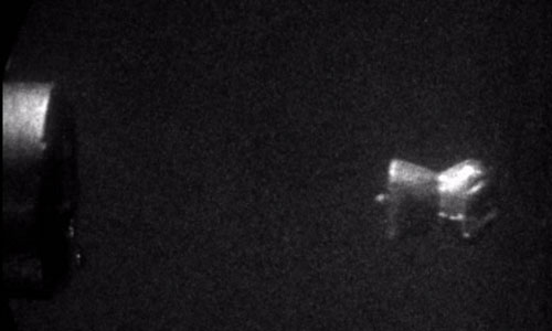
Apart from the obvious advantages of gain and intensification, the intensifier offers additional possibilities. It can serve as a fast shutter, by use of gating. At a negative cathode voltage, the intensifier is open. It closes at a positive voltage. Switching can be done very quickly and at high repetition rates, resulting in very short exposures (down to nanoseconds), synchronized with a camera that can operate at very high frame rates. Ultrashort exposure will reduce any motion smear to a minimum. The figure below shows a recording sequence of a combustion cycle of a fuel injection engine at 22000 fps, made with a gated intensified high-speed camera.
An image intensifier can also serve as a radiation converter. Images in the part of the spectrum that are invisible to the human eye (for example UV or NIR) can be converted to a different part of the spectrum that can be detected by an image sensor. The spectral sensitivity of the image intensifier is determined by the type of photocathode that is chosen.

GenICam
-
The Generic Interface for Cameras (GenICam) standard aims to provide a generic programming interface for cameras and other camera-related devices. Every step in the imaging process -from configuring the camera to getting the recorded images off the camera- can be configured using GenICam.
No matter what type of camera or data transfer interface you are using, if all your devices are GenICam compatible then it will be much easier for them to communicate.

CoaXPress
-
CoaXPress (CXP) is a communication standard for imaging data. It transfers data over one or multiple coaxial cables. The main strengths of this standard are its high transfer speeds and the long cable lengths. CXP can also power cameras with Power-over-CXP, removing the need for a dedicated power supply for the camera.
TRANSFER SPEEDS
Because of its high transfer speeds, CXP is ideal for streaming high-speed imaging. Each CXP cable can transfer up to 6.25 Gbps. Our cameras have 4 CXP ports for a total transfer speed of up to 25 Gbps.
COMPUTER INTERFACE
You need a frame grabber to capture the data that is transferred over CXP. A frame grabber is an expansion card for a computer that captures the incoming data and displays it on the screen or stores it on the computer. Most frame grabbers offer a software development kit (SDK) to develop your own specialized image acquisition software.

GigE Vision
-
GigE Vision is a framework for transmitting images over an Ethernet connection. It consists of protocols that define how to configure a camera and to transfer the image data. Every computer with a fast Ethernet card is compatible with the GigE Vision framework. So GigE Vision requires only an ethernet card, whereas CoaXPress and Camera Link require a framegrabber.
The maximum transfer speed of a GigE Vision camera (assuming a gigabit Ethernet card in the computer) is 1000 Mb/s.

Fiber-Optic Coupling
-
It is important that image quality is maintained as much as possible when using intensifiers. At the same time, light efficiency should be maximized. This can be achieved by using a fiber-optic window as the output of the first stage and as the input of the second stage.
A fiber-optic window is a solid piece of glass consisting of millions of parallel glass fibers sealed together. Each fiber acts as an independent light conductor. The shape of the window can either be flat (parallel input and output faces), or concave. Fibers with a concave surface are used for distortion correction in electrostatic image inverters.
Often the second stage will also have a fiber-optic output to allow coupling to a third stage, or to the image sensor of the camera. In the latter case the image sensor of the camera should be equipped with a fiber optic input window. In addition, take the following into consideration when you need to make a choice for either fiber-optic coupling or lens coupling:
Fiber-optic coupling is a permanent connection; the connection is made during the manufacture of the integrated intensified camera.
A fiber-optic window transfers an image from one face to the other. If the fiber optic has a tapered form, the image is reduced or enlarged. This characteristic can be used to match it to the format of a coupled imaging component.
While fiber-optic coupling between intensifiers is the standard technique, coupling to the camera can also be done by lens optics. Disadvantages of lens coupling are the greater loss in efficiency (compared to fiber optics) and the lenses are more bulky.
Lens coupling offers the flexibility of easy decoupling, allowing you a choice to make camera recordings with or without the use of an intensifier.
Camera Link
-
Camera Link is a serial communication standard. It has three main configurations: Base, medium and full.
BASE CONFIGURATION
This configuration requires one cable and has a data throughput of 2.04 GBit/s.
MEDIUM CONFIGURATION
This configuration requires two cables and it can transfer twice as much data as the base configuration. The maximum data throughput of this configuration is 4.08 GBit/s.
FULL CONFIGURATION
This configuration also requires two cables and it has a maximum data throughput of 5.44 GBit/s.
TIRF FLIM
-
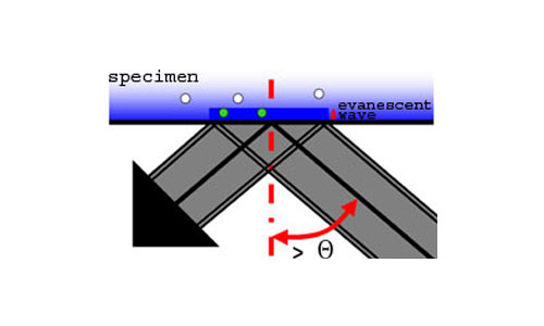
Total Internal Reflection Fluorescence (TIRF) microscopy is a super-resolution technique with high sensitivity of fluorescence near the cover glass. TIRF does not disturb cellular activity, and enables tracking of biomolecules, and the study of their dynamic activity and interactions at the molecular level. TIRF enables the selective visualisation of processes and structures of the cell membrane and pre-membrane space such as vesicle release and transport, cell adhesion, secretion, membrane protein dynamics and distribution or receptor-ligand interactions. The combination of TIRF and frequency domain FLIM makes it possible to measure fluorescence lifetimes of for instance small focal adhesions near the cover glass.
High NA TIRF objectives (up to 1.49) make it possible to introduce illumination at incident angles greater than the critical angle (θθ) resulting in TIR (Total Internal Reflection) accompanied by the formation of an evanescent wave immediately adjacent to the coverglass-specimen interface. The evanescent wave energy drops off exponentially with distance from the coverglass and reaches about a hundred nanometers into the specimen. For TIR to occur, the refractive index of the coverglass should be higher than the refractive index of the specimen (which is e.g. the case when using buffered saline solution).
The white-TIRF as well as the laser-TIRF system utilises this evanescent wave to excite fluorescent molecules in a very thin section in contact with the coverglass (here: green dots). Because the specimen is not excited beyond the evanescent wave (here: white dots), this imaging system can produce fluorescence images with an extremely high signal-to-noise (S/N) ratio and z-resolution.
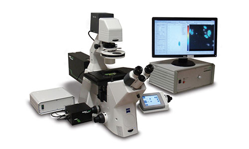
Confocal FLIM
-
Confocal microscopy is a technique for high-resolution three-dimensional imaging which uses a pinhole to increase resolution in the image plane and eliminate out-of-focus light in thick specimens. The thickness of the focal plane is generally defined mostly by the objective lens and also by the optical properties of the specimen and the ambient conditions. With an imaging confocal only the light within the focal plane is detected, so that the resulting confocal images appear crisper than widefield images. Typical applications occur within the life sciences, e.g. in cell biology. In essence there are two classes of confocal systems: single beam and multi-beam.
Confocal Scanning with CSU Spinning Disk
A Nipkow spinning disk is a multi-beam confocal scanner. The main advantage of this type of confocal imaging is the relatively fast imaging acquisition making it useful for live cell imaging applications.
The operating principle of the Yokogawa CSU spinning disk is explained here. Briefly, the disk has a spiral pattern of pinholes that is illuminated by an expanded laser beam. This generates a multi-beam illumination pattern which which the sample is illuminated. By rapidly rotating the disk this multi-beam visits all positions in the sample plane near simultaneously. The part of the fluorescence that travels back through the pinholes generates a full field confocal image at the camera detector.
Being a camera-based system, the Lambert Instruments LIFA system for frequency domain FLIM is compatible with multi-beam confocal microscopy techniques, most notably the Yokogawa CSU spinning disk series (based on the Nipkow disk scanner), and the VTInfinity series by Visitech International Ltd.
Frequency-Domain FLIM for Beginners
-
Fluorescence lifetime imaging microscopy (FLIM) can be performed in the time domain and in the frequency domain. Scanning single point lifetime detection units on confocal laser scanning microscopes mainly operate in the time domain. Camera-based lifetime detection on widefield, multi-beam confocal and total internal reflection fluorescence (TIRF) microscopes operate both in time domain and frequency domain. The Lambert Instruments LIFA for example is a fast frequency-domain system, whereas the Lambert Instruments TRiCAM can be operated both in the frequency and time domains.
TIME DOMAIN
In the time domain the fluorescence decay can be measured by using time-correlated single photon counting (TCSPC) or fast-gated image intensifiers. A measurement requires short excitation pulses of high intensity and fast detection circuits. Each point in the sample is excited sequentially. TCSPC records a histogram of photon arrival times at each spatial location using Photo Multiplier Tubes (PMTs) or comparable single photon counting detectors. Fast-gated image intensifiers measure fluorescence intensity in a series of different time windows. With both time domain techniques lifetimes are derived from exponential fits to the decay data. When sufficient channels (time windows) are used, multi-exponential lifetimes can be extracted.
FREQUENCY DOMAIN
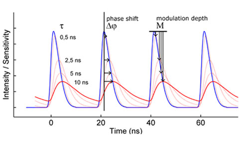
The frequency-domain FLIM technique requires a modulated light source and a modulated detector. The excitation light is modulated or pulsed in intensity at a certain radio frequency (the blue curve in the figure below). The induced fluorescence emission will mirror this modulation pattern and show, due to the fluorescence decay, a delay in time in the form of a phase-shift (the red curve). In addition, the modulation depth will decrease with respect to the excitation light, while the average intensity remains the same. The phase-shift and modulation-depth directly depend on the fluorescence lifetime and the known modulation frequency.
To extract the phase shift and modulation depth from the fluorescence emission signal, a homodyne detection method is often used. In this method the sensitivity of the detector - often an intensified camera - is modulated (or gated) with the same radio frequency as the light source (the green curve in the figure on the right). For a camera detector the result is an intensity image with a fixed brightness. By shifting the phase of the image intensifier with respect to the light source in a series of fixed steps a low-pass signal is generated for each pixel: the output image will be brighter or dimmer depending on whether the detector sensitivity is in or out of phase with the fluorescence emission. The result is a frequency-domain FLIM signal as a function of the phase difference between light source and camera (purple curve in the figure on the right) for each pixel in the image.
Fluorescence Lifetime Imaging Microscopy
-
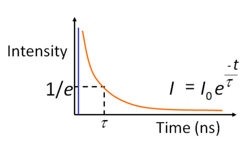
WHAT IS THE FLUORESCENCE LIFETIME?
The fluorescence lifetime - the average decay time of a fluorescence molecule's excited state - is a quantitative signature which can be used to probe structure and dynamics at micro- and nano scales. FLIM (Fluorescence Lifetime Imaging Microscopy) is used as a routine technique in cell biology to map the lifetime within living cells, tissues and whole organisms. The fluorescence lifetime is affected by a range of biophysical phenomena and hence the applications of FLIM are many: from ion imaging and oxygen imaging to studying cell function and cell disease in quantitative cell biology using FRET.
Modulated Intensifiers for Lifetime Imaging
-
As part of its portfolio, Lambert Instruments designs and manufactures ICCD cameras based on modulated image intensifiers for frequency domain imaging techniques such as FLIM. Standard products such as the new TRiCAM M ICCD camera, the TRiCATT M modulated intensifier attachment, and the LIFA system are all based on a proximity-focused modulated Gen II or Gen III image intensifier.
The modulated sensitivity of an image intensifier is produced by high-frequency switching of its photocathode voltage. In this modulation mode the temporal and also the spatial characteristics of the image intensifier are different from the nominal characteristics under continuous operation.
Spatial Resolution of Image Intensifiers
-
The limiting spatial resolution of an intensified imaging system depends on several factors, including (but not limited to)
- Image intensifier type
- Image intensifier gain
- Pixel size
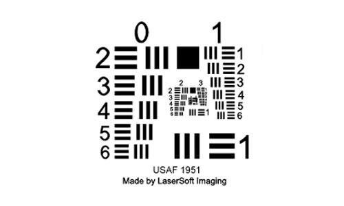
Before we can discuss each of these factors, we need to define what limiting spatial resolution means. When characterizing an imaging system, the limiting spatial resolution describes the smallest features that can be distinguished. There are several ways of characterizing the spatial resolotion, most of them use a test chart like the USAF resolution test chart. Such charts have a series of lines on them, the smaller the lines an imaging system can distinguish, the better the spatial resolution.
Spatial resolution is quantified in the number of line pairs that can be distinguised per millimeter (lp/mm). A line pair consists of a dark line and a bright line. So if one line is 5 microns wide, then a line pair will be 10 microns wide and there would be 1 mm/10 microns = 100 line pairs per millimeter.
IMAGE INTENSIFIER TYPE
There is a wide range of image intensifiers available. We advise our customers on the type of intensifier they need for their application based on the wavelengths that are important for our customers, and the frame rates they need. High-speed intensifiers usually have a lower spatial resolution than image intensifiers that are optimized for lower frame rates.
IMAGE INTENSIFIER GAIN
We can increase the MCP voltage of an image intensifier to increase its gain. But MCP noise and the size of the electron cloud at the exit of the MCP also depend on the MCP voltage, so the spatial resolution will be slightly reduced as the MCP voltage is increased. You can learn more about how an image intensifier works on our image intensifier page.
PIXEL SIZE
Finally, the limiting spatial resolution of an imaging system is determined by the size of the pixels that collect the light from the image intensifier. You can use our intensifier-sensor matching calculator to find the theoretical maximum sensor resolution. It is calculated using the size of the pixels.
For example: If the pixels are 20 microns wide, we would need two adjacent pixels to distinguish a bright line and a dark line of a test chart. Those two pixels would have a total width of 40 microns, so the theoretical spatial resolution would be 1 mm/40 microns = 25 lp/mm.
The element of the imaging system with the lowest spatial resolution determines the limiting spatial resolution of the whole system. In our example, we have a sensor that has a limiting resolution of 25 lp/mm. If we have an image intensifier with a 50 lp/mm resolution, the size of the pixels would limit the resolution of the imaging system to 25 lp/mm.
However, if the pixels are smaller, 2 microns for instance, then the theoretical resolution of the sensor would be 250 lp/mm. In that case, the resolution of the image intensifier would determine the resolution of the total system.OTHER FACTORS
Many factors influence the spatial resolution of an intensified imaging system, like the size of the image intensifier, the number of image intensifiers and the optics.
Intensified High-Speed Imaging
-
Clever use of digital cameras in combination with intensifiers and boosters allow us to create images of high-speed events, even when light is failing. In addition, fast gating offers possibilities to use extremely short exposures and to record multiple images in one frame. For creating images of events that are invisible to the human eye, like near-infrared (NIR) and ultraviolet (UV), radiation conversion techniques can be used. This technology note will review the techniques that make this possible.
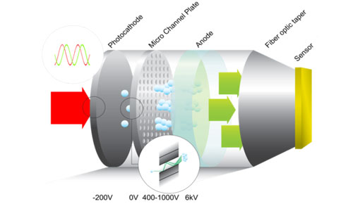
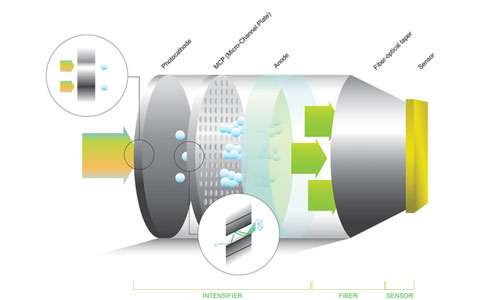
HOW DOES AN INTENSIFIER WORK?The image intensifier is a vacuum tube with a photocathode at the input, a micro-channel plate (MCP) in the middle and a phosphorescent screen at the output. Photons are processed as follows:
The image is projected onto the photocathode. The photocathode converts the incoming light (photons) into electrons. The electrons are emitted in the vacuum tube and accelerated towards the MCP by an electric field.
The MCP is a thin plate consisting of many parallel micro channels; each channel works as an electron multiplier by secondary emission from the channel wall. The gain of this multiplier depends on the voltage that is applied between the input and the output of the MCP. Typical electron gain is in the order of 10,000. At the end of the channel, the electrons are accelerated by an electric field towards the anode screen.
The anode screen is a phosphor layer deposited at the vacuum interface of the output window; it is covered by a thin aluminum film to prevent light feedback. The anode screen has a potential of 6 kV with respect to the MCP. The electron energy is absorbed by the phosphor material and converted into light. The result is a visibly intensified image at the output of the intensifier.
The output window of the intensifier is usually fiber-optically coupled to the next component. This can either be the image sensor or to a next stage of the intensifier.
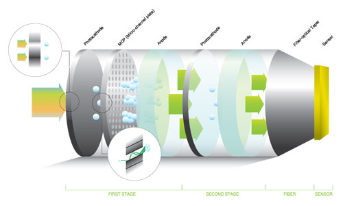
Dual-Stage Image Intensifier
-
In very low-light situations or when a very short exposure time is required, a dual-stage image intensifier may be required. The first stage is the same as a single-stage image intensifier; it has a micro-channel plate that multiplies the electrons emitted by the photocathode. The second stage is often referred to as a booster. This stage does not have a micro-channel plate, it multiplies the incoming photons without the saturation characteristics of a micro-channel plate.
DUAL-STAGE IMAGE INTENSIFIER WITH FIBER-OPTIC COUPLINGThe figure below shows a schematic representation of a dual-stage image intensifier that is fiber-optically coupled to the image sensor. The first stage is similar to a single-stage image intensifier.
Intensified High-Speed Cameras
-
Normal consumer cameras operate very well in day-light, or room ambient lighting conditions. However, when you want to make a snapshot of a fast moving object, exposure-time has to be shortened to obtain a sharp image. This comes with a cost; images are much darker when using a short exposure time. At a certain threshold, the attenuation has to be compensated. This could be done by increasing the light (by using a flash), or by improving the photo-sensitivity of the camera. In high-speed cameras this effect is even stronger.
To get clear images in high-speed cameras, an object has to be illuminated with a high intensity light-source. The higher the frame rates the shorter the exposure time per frame, the higher the intensity of the light-source must be. In many applications increase in illumination is an adequate method to compensate the shorter exposure times. However, in some applications the object itself is emitting light, or is influenced by the light-source. In combustion research, for example, or imaging of dynamic phenomena in fluorescent biological cells, or low intensity PIV, light intensities are too low to record with conventional high-speed cameras. In applications like microfluidics, the heat generated by a powerful light source can have a tremendous effect on liquid flows.
To apply high-speed imaging in the forementioned situations, Lambert Instruments has developed intensified high-speed cameras and high-speed intensifying camera attachments. The special two stage high-speed image intensifiers in these products amplify the input light to a typically 10000 times higher level on the output. This makes it much easier to distinguish an image from the noise. Furthermore, the gating feature of the image intensifier makes it possible to capture even the fastest objects without motion blur.
Low-Light Imaging
-
Ever since the invention of the digital camera, new imaging applications have been explored. The increasing possibilities of fast digital cameras have resulted in applications that were unthinkable only twenty years ago. High-speed cameras nowadays are widely used for recording of dynamic events at high frame rates (e.g. 10000 fps). The results can then be inspected by playing individual frames at a lower speed.
High-speed imaging up to 100000 fps is easily feasible with current technology. But what if you need to create high-speed images when light conditions are far from optimal? Your high-speed camera will be no good under these circumstances, as a certain brightness of the object is required for the high frame rates that are used. The lack of light in combination with short exposure times will result in underexposed and noisy images. The obvious solution would be to increase the illumination level of the object. However, in some cases it is just not possible to add more light, for example because:The object to be recorded generates light by itself. This may be the case for phenomena like the combustion process (flames and turbines), or in living cells that emit fluorescent light.
The radiation level corresponding to the required brightness would cause an unacceptable temperature rise of the object.
And what if the image signal has become too low because of the high frame rates? Camera noise will be an additional problem then. Fortunately, there is a high-tech solution for these problems: the image intensifier. It is used to intensify the image before it is projected onto the image sensor of the high-speed camera. The intensified image results in a sensor signal that is typically 10 000 times higher than without using an image intensifier—in the process elevating the signal above camera noise level.
Intensified CCD Cameras
-
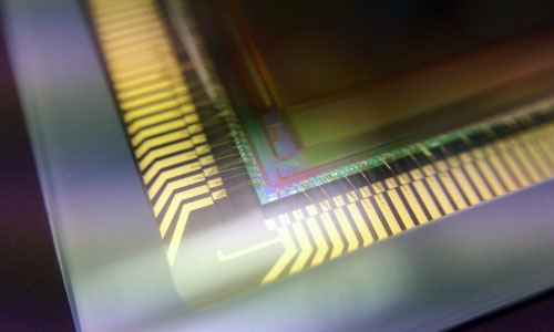
An Intensified CDD (ICCD) camera is an electronic camera, equipped with an intensified CCD as image sensor. The sensor uses an image intensifier that is fiber-optically coupled to the CCD chip to increase the sensitivity down to single photon level.
An intensified CCD camera allows image acquisition at very low light levels over a wide light spectrum and at relatively high speeds. Single photons can be detected and discriminated from CCD noise. Ultra high-speed phenomena can be captured by using the image intensifier as a fast shutter (gating).
CCD Camera Sensitivity
-
At low light levels standard CCD/CMOS cameras are not sensitive enough to capture useful high-contrast images. There are ways to increase the sensitivity of such cameras. The first method is to allow the CCD to integrate for much longer times. In order to prevent high background noise, CCD cooling is applied when using long exposure times. A second method is to use an image intensifier to boost the input signal.
COOLED CCD
At longer integration times of a CCD, more light is captured to enhance images. However, not just more input signal is collected, but also more dark current from the CCD itself. The amount of dark current depends strongly on the temperature; for every 6 degrees C the CCD is cooled down, the noise (dark current) halves. When the CCD is cooled to -25 degrees C, integration times up to minutes can be applied. This enhances the sensitivity of the camera immensely.
To better improve the cameras SNR, the read-out noise is reduced by using a lower read-out speed. These techniques are used in high performance 14 and 16 bits digital cameras.
INTENSIFIED CCD WITH FIBER-OPTIC COUPLING
An image intensifier helps to increase the sensitivity of a camera by amplifying the input light-signal before relaying it to the CCD/CMOS sensor of a camera. Roughly, there are two ways to relay the output image, from an image intensifier, to a CCD/CMOS sensor. The first is by means of a relay lens. A lens coupling is flexible, but the downside is that a lens coupling has a low transmission efficiency, caused by the limited aperture of a lens. A more efficient way is to use a fiber-optic window to transfer the image from the intensifier to the CCD. A fiber-optic window contains a large number of microscopic (6-10 micron) individual fibres and acts as an image guide. A tapered fiber-optic window will magnify or demagnify input images. Generally, demagnification is chosen to match the image intensifier to the CCD/CMOS sensor.
In summary, the advantages of a fiber-optic coupling are:- Low light losses
- Intensifier/CCD combination is more compact
- Camera design is sturdier
- No optical adjustments are needed
Third Generation Image Intensifier
-
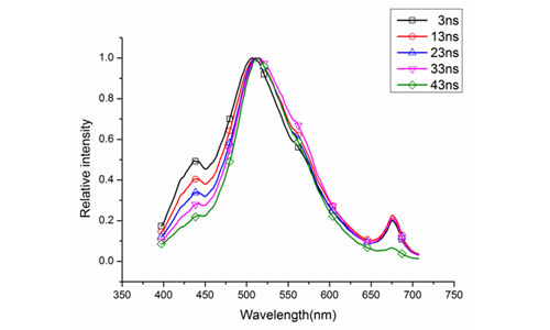
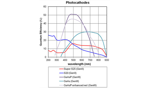
The next step in technology is the third generation (GenIII) image intensifier in which the multi-alkali photocathode is replaced by a Gallium-Arsenide (GaAs) or a Gallium-Arsenide-Phosphide (GaAsP) photo-cathode. The quantum efficiency (QE) of these types of photo-cathodes are much higher as compared to the multi-alkali photocathode of the second-generation image intensifiers.
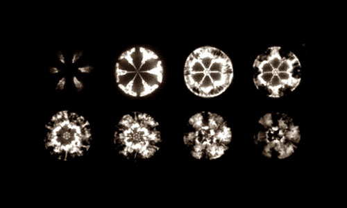
Recently, new filmless Gen III intensifiers have been developed that are using the high QE to its full extend. The higher QE results in a better SNR or in shorter exposure times at equal SNR. In the graph, spectral sensitivity curves of multialkali photocathodes, such as S25, S20 and broadband, are shown in comparison with GaAs and GaAsP photocathodes.
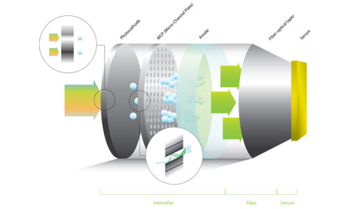
The Image Intensifier
-
An image intensifier is a device that intensifies low light-level images to light levels that can be seen with the human eye or can be detected by a camera. An image intensifier consists of a vacuum tube with several conversion and multiplication screens.
An incident photon will hit a light sensitive photo-cathode screen. Photons are absorbed in the photocathode and give rise to emission of electrons into the vacuum. These electrons are accelerated by an electric field to increase their energy and focus them on the multi channel plate (MCP).
Inside the MCP the electron image is multiplied, after which the electrons are accelerated towards an anode screen. The anode screen contains a layer of phosphorescent material that is covered by a thin aluminium film.
The anode contains a phosphor such that when striking the anode the energy of the electrons is converted into photons again. Because of the multiplication and increased energy of the electrons the output brightness is higher as compared to the original input light intensity.

Intensified Cameras for Lifetime Imaging
-
Intensified cameras enable full-field frequency-domain and time-domain FLIM. The image intensifier becomes an ultra-fast electro-optical shutter by operating it at radio frequencies allowing time-resolved imaging. The high-resolution image intensifier is the key component of the TRiCAM (part of the LIFA) and the TRiCATT camera attachment. Its photon gain is typically in the range of 100 to 10000. Lambert Instruments provides different image intensifiers based on photocathodes with different spectral sensitivity to match a range of applications in the UV, visible and NIR.
For FLIM in the lifetime range of 0 ps to 1 ms we provide S20 (UV) and SuperS25 (visual) image intensifiers. For increased quantum efficiency of the photocathode in the visual part of the spectrum in this lifetime range, a GaAs intensifier is available. For near-infrared applications up to about 1100 nm an InGaAs photocathode is available.

Frequency-Domain FLIM: Basic Equations
- In this article the first principles of frequency domain (FD) fluorescence lifetime imaging microscopy (FLIM) are further explained through use of equations. Although these principles not necessary for the execution of basic lifetime measurements, a thorough understanding provides the groundwork that enables deeper insight into your results and into the possibilities of FD lifetime imaging.