- Offer Profile
- The Service Robots Group -
works on different service robot projects as:
- Unmanned ground robots,
- Climbing robots,
- Rapid prototyping,
- Unmanned aerial vehicles,
- Biped robots
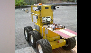
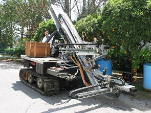
U-Go Robot: Unmanned Ground Outdoor Robot
- U-Go Robot is an acronym for "Unmanned Ground Outdoor
Robot". This robot has been developed at DIEES Robotic Laboratory mainly to
solve problems like transportation, navigation and inspection in very harsh
outdoor environments. The robot is currently used as a multifunctional
vehicle able to operate inside greenhouses or vineyards for precision
farming applications, to perform inspections into volcanic environments and
as a test bed for new GNSS (Global Navigation Satellite System) localization
technologies in order to test generic outdoor navigation algorithms. The
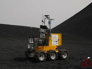
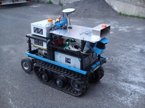
robot two main dimensions are 0.6 m wide and 1.2 m long. Moreover it uses
rubber tracks instead of wheels for locomotion and its weight is about 250
kg. Four 12 V - 80 Ah sealed lead-acid batteries are mounted on the
mechanical structure on the rear side of the robot. Each rubber track is
actuated by means of a 24 V - 650W brushed DC motor and suitable gearboxes
are mounted in the front side of the robot.
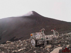
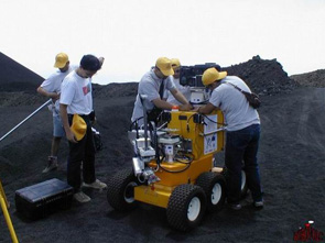
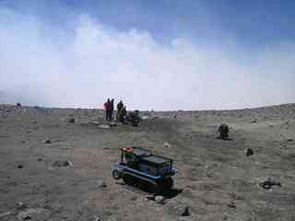
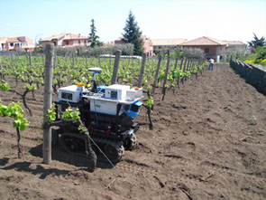
U-Go Robot allows tele-operations by means of a remote wireless joypad. Different tests using this guidance methodology have been done mainly on the Etna volcano and on the Volcano island. During these tests, transportation capabilities in very rough outdoor environment have been tested. The on-board sensors suite is composed by Stereo Camera, Webcam, X-Sens MTi Attitude and Heading Reference System (AHRS), Laser range finder (LRF), Bumpers, UltraSound Sonars, Global Navigation Satellite System (GNSS) or DGPS receiver. Moreover there are two dual-core computers; one is used for navigations purpose while the other is used for artificial vision purpose.
By using these sensors or a subset, different navigation algorithms have been implemented. For example, using a DGPS receiver and a Laser range finder, a navigation and obstacle avoidance algorithm based on the potential field theory (PFM), has been implemented. By using the stereo cameras set, different road following and obstacles avoidance algorithm have been tested. AHRS unit is used in order to compensate different sensors for road slope. By using ultra sound rangers and webcam, a navigation algorithm able to move the robot between greenhouses corridors has been implemented.
Different tests of these algorithms have been performed in greenhouses, vineyards and open fields. These tests have been made in cooperation with DIA, University of Catania, Mechanical section that is conducting different research in the field of precision farming. The U-Go Robot is used as a 'carrier' for different tools as automatic sprayers. The robot has been used also during the M-Elrob 2010 trials in order to test the system in a very demanding environment.
Electro Climb: A Climbing Robot that use electrostatic adhesion
- The electro-adhesion exploits the electrostatic force
(explained by Coulomb's law) between the material that serves as a
substrate, and the electro-adhesive pad. The pad is generally made up of
polymer coated electrodes or simply by conductive materials. When the
charges are induced on the electrodes, the field between the electrodes
polarizes the dielectric substrate causing electrostatic adhesion. It is
essential to maintain the electro-adhesive pad and the surface in close
contact, since the electrostatic forces decrease dramatically with the
square of the distance. The basic idea is to create structures with two
electrodes that have shape, size and distance requirements that ensure a
high electrostatic field and that generate high adhesion forces on different
types of material as wood, glass, paper, ceramics, concrete, etc.
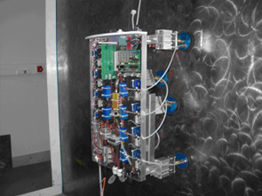
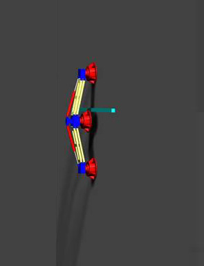
Different kinds of structures have been tested after FEM simulations. Some initial trials have been done using inter-digited polyethylene coated structures. As this kind of structure showed very poor results, devices with parallel electrodes have been realized and tested. The final structures are obtained by thermal fusion of two polypropylene layers with a thickness of 25um, heated up to 120°C and pressed with high pressure with rollers on both sides of aluminum electrodes. The structure obtained has a high strength, flexibility and a high coefficient of static friction with the substrate on which it is applied. Using this kind of electro-adhesive pads, a tracked climbing robot has been developed and tested. For this application "Peeling" methodology of multiple electro-adhesive pads has been exploited. This methodology allows to further improve performances in terms of pad adhesion, total payload and travelling speed. The electro-adhesive track has been realised by fitting different pads on a flexible roller-chain.
The MOW-BY-SAT Project: "Mowing the lawn by satellite"
- The priority objective of the MOW-BY-SAT project is to
support the development of a GNSS based navigation and guidance system to be
integrated into an autonomous lawnmower, paving the way for
industrialisation and commercialisation of GNSS applications oriented to
domestic service robot, operating outdoor. Up to now, GNSS technologies are
not much used in robotic applications. Beyond this concrete application the
project aims to increase the adoption of the GNSS technologies towards
robotics application, in a relation M2MM (Machine to Mobile Machine). In
this context the project will study the benefits of European GNSS (EGNOS and
Galileo). The research leading to these results has received funding from
the European Community's Framework Programme (FP7/2007-2013) under grant
agreement n° 227824.
Our idea, source of this project, is to increase the adoption of GNSS towards domestic robot applications, like autonomous mowers, which do not currently use GNSS at all for their guidance systems. This would generate economic and social benefits like reduced pollution (lawn mowers with thermal engines frequently have poor tuning and proportionally higher CO2 emission), and decreased domestic accidents rate (too numerous accidents with mowing machines are observed anywhere in the world). In addition it will pave the way for Galileo which, combined to GPS/EGNOS, will dramatically increase the availability of decimeter protection levels, enabling then others robotic applications. The scientific objective of the project is to demonstrate that a local augmentation with the combination of a specific phase processing and EGNOS/EDAS data provides the GNSS receiver with an acceptable risk of non-integrity for a few decimeters protection radius (innovative and unique integrity tuning). In the short term, that will enable the use of GNSS in domestic robotic area, where the service availability is not very stringent like lawn mowing. The project will also demonstrate that the future Galileo signals will allow many safe land activities in robotic, consequently triggering the proliferation of GNSS in several new mass markets segments in this domain. The technical objective of the project is to implement the above scientific concept in a prototype of the cheapest stand alone GNSS technology allowing a lawn mower robot to perform its full mission in an efficient and autonomous way, like a golf keeper would do it safely in such a complex operative area.
RAPOLAC: Rapid Production of Large Aerospace Components
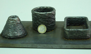
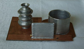
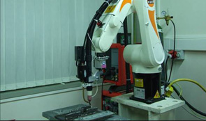
- The Shaped Metal Deposition (SMD) process is a novel manufacturing technique developed and patented by Rolls-Royce in order to produce mechanical parts directly from a CAD model. The work developed has been carried out in the frame of the RAPOLAC EC project (www.RAPOLAC.eu), and aims to investigate upon an automatic control system, in order to free the operator from constant monitoring and manually acting on the welding process parameters. The innovative aspect of the SMD process consists of reversing the production philosophy actuated up to now, by the traditional rapid prototyping methods, such as machining. This method is based on the material remove from the work piece, in order to obtain a desired final shape. There are several evident drawbacks in this process, like the large waste of material in scraps and the consequent increase of the costs, depending of the material used. The SMD process reverses this destructive production philosophy and works by adding progressively the material to the final work piece, in order to obtain the desired shaped component. This means that effectively no process scraps are produced minimizing the material used to the strictly amount required by the final work piece shape. Two versions of the SMD plant have been developed. A TIG welding machine working together with a KUKA industrial manipulator has been set up for melting stainess steel (upper figure). Also a three axis CNC machine has been used as a small scale version of the SMD plant for melting tin (right figure).
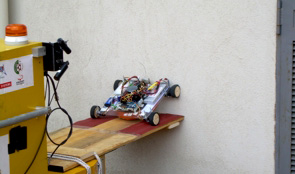
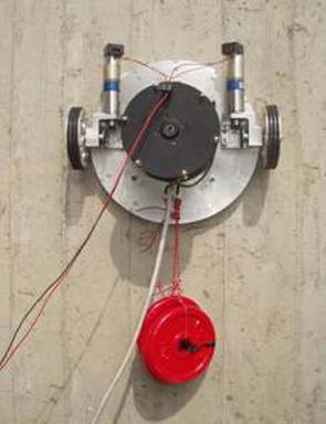
Alicia VTX: A Vortex-Based Sliding Suction Cup Climbing Robot
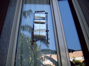
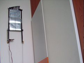
- The Alicia VTX is a new climbing robot that use a
smart active suction cup, built upon an idea of Duke University. The vacuum
inside the cup is generated by means of a high speed centrifuge fan that
create a vortex with a low pressure area in the central zone. By using this
principle it is possible to use a low power brushless motor to actuate the
fan (about 50W). Moreover no exhausts are generated, so the process is more
efficient with respect to suction cups where an aspirator is used instead to
generate the vacuum.
This kind of vacuum cups can adhere to different kind of rough surfaces because it can sustain vacuum inside also in the case when the cup is not in contact with the surface. This allows to reduce to zero the friction between the cup and the wall, to save energy, to increase robot speed, allows the robot to move over small obstacles or irregularities and to climb from a floor to a wall while maintaining high payloads (about 1.5 kg).
The robot use four wheels with four independent DC motors to move along the surface and use an inclinometer as feedback sensor in order to follow a reference trajectory. Moreover a wireless CCD camera is mounted on-board. Different tests about the cooperation between the Robovolc rover and the Alicia VTX were performed in order to investigate the possible use of the two in outdoor environment in critical situations where human operator can't reach the target vertical wall and can't perform visual inspection for safety or rescue purpose.
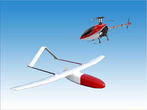
UAV: Unmanned Aerial Vehicle for flying over volcanoes
- The key project in the field of Unmanned Aerial
Systems is represented by the Volcan UAV, designed to study the composition
of gas inside volcanic plumes. The main aim of the system is that of flying
inside the plume (volcanic cloud) to directly analyze the concentration of
the main components of the fumes (HCl, SO2 and CO2), but also the pressure,
the temperature and the wind speed. The system must be capable of flying
autonomously at up to 4000m altitude with a payload of 5Kg using electric
motors, to avoid contaminations with the gas sampling system, at a cruise
speed of 40km/h.
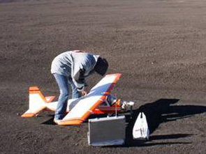
The electronic control system and the measurement systems have been designed, built and tested and are currently employed on the plane.R&D in the field of UAS covers several aspects related to the topic of flying platforms:
Autonomous Navigation
Stability and waypoints navigation algorithms have been developed and tested and are currently employed on the fleet.
Sensors Units
Inertial Measurement Units (IMU), Air Data Attitude and Heading Reference Systems (AHRS), Inertial Navigation Systems (INS), calibrated and compensated compass have been realized by making the most of sensors fusion algorithms.
Extended Kalman Filtering, quaternion algebra, sensor modelling have been examined in order to develop noise-free calibrated sensors units able to guarantee high performance in all conditions and environments.
Control algorithms self-tuning
Autonomous navigation algorithms often require a certain number of hours of flight tests to determine the best values for the parameters involved in the control loops. Self-tuning procedures are actually under study to make fast and easy values determination, allowing a reduction of field trials.
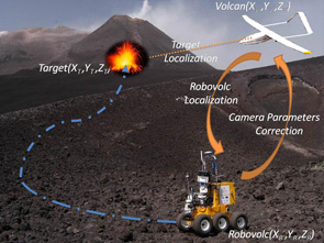
Computer Vision Algorithms
Images coming from UAVs are used for target detection and localization, for moving targets (UGV) tracking , for UAV position estimation, to detect safe landing areas for UAV.
UAV-UGV cooperation
Several studies have fully demonstrated the benefits coming from the cooperation between heterogeneous set of machines: the integration of data coming from several type of sensors and from different points of view allows to increase the informative contents, leading to a “cooperative perception”. In this sense, UAV and UGV represent complementary vehicles, the use of whom represents, together an integrated sensors network, a powerful surveillance and monitoring system. UAVs (Volcan) are used for area overseeing and emergency communication and terrain morphology changes detection, UGVs (Robovolc) are involved in area approaching and sampling and measuring operations.
Hardware In the Loop (HIL) architecture
The “Hardware in Loop” (HIL) architecture represents a powerful and cheap method to test and tune control systems. The case of tuning devices involved in the aeronautical field is very critical, since experimental trials are performed with time-consuming test flights and unsatisfactory results could lead to dangerous situations. An HIL simulator cannot fully replace field experiments, but it is very useful, especially in the preliminary phases, to discover and solve various kinds of problems. Therefore, the major aim of an HIL platform regards improvement in development time, cost and risk reduction. Once the performance is suitable for the application, the same controller hardware can be directly connected to the real UAV. In the figure above the developed architecture is represented. In this case study, the X-Plane flight simulator by Laminar Research, was adapted to the Volcan UAV: a model of the real aircraft was developed to determine the flight parameters; AHRS and GPS data are sent out to the autopilot through a CAN Bus, using a dedicated plugin and using the CANaerospace protocol. The block named “Autopilot” is the real electronic board while the HMI runs on a separate PC.Simulation tools development
X-Plane flight simulator and Google Earth based simulation tool are used to develop and validate control, navigation and stability algorithms. Moreover, the implemented tools are used to implement and test aerial target geo-localization algorithms: the software allows to simulate a camera mounted on an airplane and to use the collected virtual images to test methods for the detection and localization of ground targets. A geo-localization algorithm based on an Extended Kalman filter has been implemented by using the developed tool.
Vision Based Tracking for a Coaxial Helicopter
The cooperation between a coaxial helicopter and the “MORDUC” Unmanned Ground Vehicle is under study in order to create a robotic system based on the adoption of heterogeneous unmanned vehicles. A vision algorithm able to estimate the position of a coaxial helicopter was developed; the implementation of a discrete Kalman filter allowed to obtain more accurate and less noisy data values. The dynamic model of a coaxial helicopter was derived and used in order to create a vision-based control system that would allow a three-dimensional tracking. A PID based algorithm was implemented to control the helicopter pose; both empirical and analytical based calibration procedures were adopted to obtain the most performing parameter values.
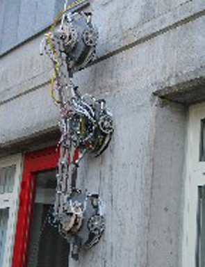
Spiderbot II: A climbing robot for industrial inspection
- Spiderbot II is a new climbing robot developed in
cooperation with Automation Service srl, in the framework of a regional
research project. The aim of the project is to realize a prototype of
climbing robot, able to work in harsh industrial environment. The robot can
perform NDI (Non Destructive Inspection) using different moving video
cameras and other sensors (like gas sensor), while a remote operator can
drive the robot and read on-board sensors from a base station placed in a
safe area. The video cameras images are sent over an analog RF channel in
the 2.4GHz band. The main structure of the robot is based on the same
principle of the Spiderbot robot (developed in past research activities) and
is composed by two sliding frames pneumatically actuated. The internal frame
can slide and rotate with respect the external one. Each frame has four
standard suction cup for adhesion to any kind of non-porous surfaces with
medium-low roughness. The suction cup are suited for harsh environment like
oily, scratched or dusty surfaces. Moreover they are also pneumatically
actuated, to allow robot steps. The entire structure is built aluminum alloy
and weights about 20 kg. The actual payload is about 5 kg. With respect to
the Spiderbot project, the new system has been better designed as regards
gripping and payload specification. Moreover robustness of the communication
protocol over an RS485 channel between robot and base station has been
improved.
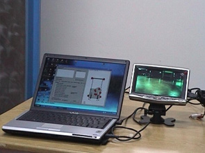
The base station is actually composed by a standard PC with an RS485 serial interface, a software that allows to control the whole system, a monitor with analog input to show robot cameras images, a joystick that allows friendly user interface, a 6 bar compressed air source and a low voltage power supply system for the robot. The connection between robot and base station is optimized for about 30 m length. Different test over real surfaces have been performed in indoor as well as outdoor environment.

From Alicia II to Alicia3: A Single Sliding Suction Cup Climbing Robot
- The Alicia II and the Alicia3 systems are two climbing
robot for inspection of vertical surfaces. To keep the operation of the
system independent from the surface material (non-porous), pneumatic-like
adhesion has to be used. The most common way to do this is by using suction
cups and a vacuum generator. Such a kind of gripping system has normally to
be mounted on a structure that is able to generate steps, because
traditional suction cups cannot slide over the surface while attached. This
kind of structure requires complex kinematics and actuators system and
generally leads to slow and heavy robots. The main idea was to build a robot
that is a suction cup itself that is able to slide over the wall surface
while staying attached.
The structure of the Alicia II module is composed by a cup with 30 cm diameter. On-board is mounted a centrifugal aspirator and its electrical motor. The aspirator is used to depressurize the cup so the whole robot can adhere to the wall like a standard suction cup. The motor/aspirator set is a very robust one and is capable to work in very harsh environment. While the system has to move over the target surface, generally represented by rough metal surface or concrete wall, the cup must not adhere with high friction, so a particular kind of sealing between the wall and the robot has been realized. This configuration allows the robot to overcome obstacle of about 1 cm and to climb a vertical surface with a minimum curvature radius of 1.8 m. The whole structure has been designed to contain onboard two wheels with two independent DC motors/gearboxes/encoders. The total weight of the module is 4 Kg all included. The used DC motors/gearboxes are able to move a mass up to 6 Kg along a vertical direction with a maximum speed of 2 m/min.
The Alicia II robot has limited capabilities in passing over obstacles higher than about 1 cm. This limitation is mainly due to the maximum height of the flexible cup sealing that cannot be higher than a few centimetres. The basic idea for the Alicia3 robot is to use three of the Alicia II modules linked together in series by means of two rod, to allow the whole system to deal better with obstacles on the target surface.
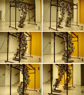
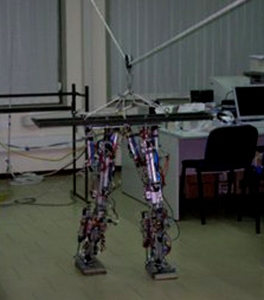
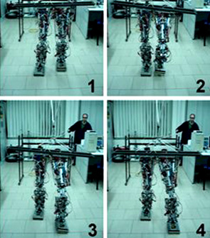
Biped: Anthropometric Robotic Leg
- The spirit that aims the present work is to investigate upon the walking ability of legged machines pneumatically actuated, with particular reference to biped machines. In particular, a complete medium height human inspired robotic biped has been designed and realized within the laboratories of the robotics department at the University of Catania. The mechanical structure of each leg is made up of four links, corresponding to the pelvis, thighbone, shinbone and foot respectively, jointed by three joints and five degrees of freedom (Dof). In particular the knee joint is moved by one rotational Dof, whereas the ankle and the hip joints, are realized through an universal joint implementing the pitch and the roll Dof for each articulation. As it is possible to see, the whole structure is very compact and reflects the typical anthropometric mass distribution of the human beings. The link dimensions are also human inspired, so the femur is 40 cm long whether the tibia is 35 cm long. Thus, the whole structure is about 110 cm high from the ground, for a total weight of about 12 Kg for each leg.
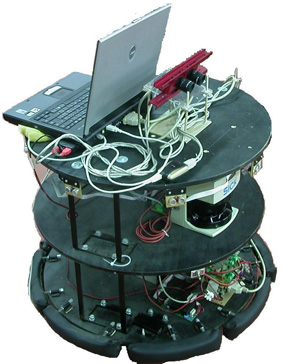
3MO.R.D.U.C.: 3rd version of the MObile Robot DIEES University of Catania
- The 3MO.R.D.U.C. is a wheeled mobile robot with a
differential drive kinematic configuration. This open robotic platform was
successfully used in localization and navigation experiments. The robot
structure has three shelves linked together. On the lowest shelf, two lead
batteries (12V/18Ah) provide the power supply. The robot autonomy is about
30-40 min. for continuous working. The on board electronic rack controls
each module of the robot (motion, sensors and communication modules).
Several sensors on board monitor the workspace and the robot state. A belt
of bumpers (16 switches) around the entire perimeter is mounted on the robot
base, just over the wheels level. These sensors recognize and reduce damage
in case of a collision. The two robot motor axes are equipped with
incremental encoders (resolution of 500 pulses per turn). These sensors are
useful to calculate heading and position of the robot by using the kinematic
model. To detect obstacles on the workspace the robot has an on board Laser
Measurement Sensor (LMS) and a sonar belt (8 sonars).The LMS operates by
measuring the flight time of a pulsed laser light beam that is reflected by
obstacle. An internal rotating mirror deflects the transmitted pulsed laser
beam so that a scan is made Stereoscopic Robot Teleguide based on Laser and
Video sensors of the surrounding area. The time between transmission and
reception of the light pulse is directly proportional to the distance
between the scanner and the object. The sonar sensors measure the distance
from an obstacle using the flight time of an ultrasonic signal produced by
means of a vibrating piezoelectric sensor. On the robot there are also two
high quality stereoscopic cameras; each one has a resolution of 1.3
Megapixel; they are equipped with fixed focus lens of 4.0 mm.
The CCD sensors of these cameras have a good noise immunity and sensibility; moreover, it is possible to adjust all the image parameter, e.g.
exposure gain, frame rate, resolution. The cameras are mounted on a rigid support; it permits to simply adjust the camera distance in a range 5-20 cm.
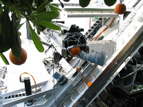
OPR: Orange Picking Robot
- The robot, which is currently available in the C.R.A.M.
laboratories, comprises a trolley which allows moving autonomously among the
rows of orange trees, and two picking arms controlled by visual feedback.
Each arm is equipped with a camera to identify and centre the fruit. Inside
the pickers two pneumatic actuators control the jaw and clippers and a third
one command a sliding tray placed at the bottom of the pincers, which slides
out before the stalk is cut. The presence of this tray, along with the
lengthening of the lower jaw, allows the orange to remain trapped inside
The degrees of freedom the manipulator is endowed with, allow scanning and picking in an diagonal direction, while the forward movement of the trolley advances to the next picking area.
An equally important feature is the integrated handling system to facilitate arrangement of the crates, thus enabling almost immediate transportation.
Robovolc: "A Robot for Volcano Exploration"
- The main objective of this project is the development
and trial of an automatic robotic system to explore and perform measurements
in a volcanic environment. A major aim of the proposed robot will be that of
minimising the risk for volcanologists who are involved in work close to
volcanic vents during eruptive phenomena. Observations and measurements of
the variables relating to volcanic activity are of greatest interest during
paroxismal phases of eruptions, which unfortunately are also the time of
greatest risk for humans.
Technical objectives of the project are :- The design, implementation and trial of a prototype robot suitable for autonomous and/or semi-autonomous exploration of natural and extremely rough unstructured environments.
- The design, implementation and trial of a small measurement system for lava and volcanic gas analysis and sample.