- Offer Profile
The research activities of the laboratory are mainly focused on the study of parallel mechanisms and articulated robot hands, two areas in which the laboratory has acquired an international reputation. Our research also includes projects on walking robots, deployable mechanisms, the use of rapid prototyping in robotics and other areas.
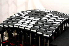
[ VOILES | SAILS ]: Flying cubic robots
- [ VOILES | SAILS ] is an art/science/technologie
research-creation platform initiated by Nicolas Reeves, a professor and
researcher-creator at the design school of UQAM. It was born from professor
Reeves' will to evoke the age-old myth of an architecture freed from the law
of gravity by the mean of a contemporary sculpture. Many challenges had to
be solved in order to achieve this result, and many skills and expertises
were required. Standing at the crossroad between art, architecture and
science, the [ VOILES | SAILS ] project aims to bring together researchers
from the artistic and scientific domains to collaborate.
STRUCTURE
Considering that the load of a cube includes the structure (about 2500 g), the polyurethane films (about 1500 g), the CPU, the motor controllers, the sensors, the wireless card, the batteries, eight to twelve motors and their polycarbonate ducts, a camera and dozens of meters of wires and cables, the optimisation of each element's weigth-to-efficiency ratio must be very carefully studied.
Several design constraints had to be considered:- The necessity to obtain a perfect cube, with straight edges and flat faces. It relates to the intention of creating perfectly geometrical flying shapes, but it is also induced by the fact that the cubes need to assemble while flying. If the edges are not perfectly straight, or if the faces become convex the cubes will not assemble properly.
- The self-assembling properties. When two cubes connect to each other, they must still be able to use their motors to move in space. The thrusts of the motors of two connected cubes must add up in order to provide enough power to move them all. This led to the decision to place the ducted fans at the midpoint of each edge, and to guide the air streams towards the corners of the cubes with thin polycarbonate tubes.
- The location of the sensors. The cube is by no way an optimal shape when it comes to sensory aptitudes, especially with large cubes (edge 160 cm or more). Obstacle avoidance would ideally require 24 sensors (one for each axis on each edge), which is hard to implement for reasons of cost, payload and energy requirements. The optimal sensor configuration is continuously being studied and updated for each project's needs.
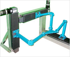
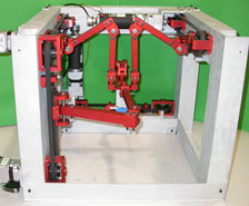
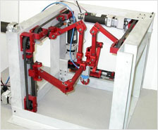
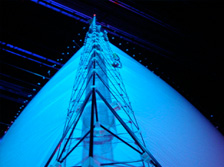
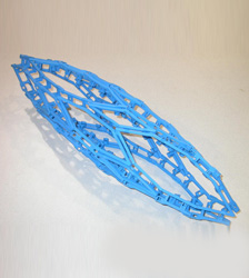
After many design iterations and prototypes the structure reaches a stable stage with the last aerobots, christened t225c (edge length of 225 cm), the Tryphon. Its exosqueletton is made of twelve triangular trusses of carbon fiber rods and tubes assembled together by rapid prototyping joints.
SENSORS AND SOFTWARE
The mechatronic of the SAILS robots was developed in order to easily accept various sensors configuration. All the components are connected to an I2C communication bus managed by the central ultralight, Linux-based computer. Until now ultra-sounds sensors, light sensors, compass, altimeter have been tested and used for performances and demos. A video camera and accelerometer will be installed onboard in the very next phases. The sensors configuration can be quickly modified, thanks to quick-connect hubs.
The embedded control software has two mode: autonomous or teleoperated. This last mode allows the user to command position (through a USB numeric pad) which the controller then tries to stabilize. The autonomous mode is currently based on reactive behaviors. The two first automous algorithms were to stabilize itself according to a desired distance from a wall or a floor, and avoid obstacles while moving around. They use data collected from 12 ultrasounds sensors that have a 6-meters detection range. Many others specific behaviors were developed to trigger reactions to the robot's environment.PAST PERFORMANCES AND FUTURE WORKS
The SAILS prototypes have been shown during major art events in several countries: Canada (Quebec Museum of Civilization), Belgium (Antwerpen Museum of Fashion), France (Grand Palais, Paris), Russia (Moscow Winzavod Center) and Czech Republic (Industrial Palace, Prague), among others. They also participated in several educational events.Future developments involve the enhancement of the robustness of the aerobots for theatrical performances and public events; revision of the software to ensure maximal reliability during interactions with actors, so that planned interactions can be faithfully repeated in every performance; implementation of in-board camera/acceloremeter based control in order to give the aerobots a better knowledge of their pseudo-absolute position and microphones to open new human interaction possibilities.
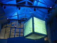
- ryphon prototype from the project [ VOILES | SAILS ] with video projections by Jason Lewis
- Focus on the structure of one truss
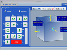
- [ VOILES | SAILS ] Java Interface
- Robofolies — Montreal Center of Sciences
- ScienceArtFest — Winzavod gallery of Moscow
SMALL WALKING ROBOT: ALL-TERRAIN PLATFORM (PROMPT)
- Martian exploration will evolve at the dawn of 2020
towards robots at the restricted cost, reduced dimensions and the mobility
adapted to the rough terrains which are rich in geological information.
Canada being an international leader in space robotics, a participation in
these missions seems a natural evolution of its program. With an aim of
developing a bank of solutions specific to planetary robotics, the
Department of Space Technologies of the Canadian Space Agency entrusted us
the mandate to design and protoype a small walking robot platform.
Our principal objectives of design were to create a simple and reliable platform able to move on a rough terrain without finding itself in a position that would make it unusable, while minimizing dimensions, the mass, the number of actuators and the power consumption. The prototype is the result of analytical and numerical studies of kinematics and dynamics carried out on several geometrical models.
With only two motors actuating its six legs, the robot has a simplicity of control which goes hand in hand with the specifications required by the space context of the project. It has mechanical reflexes enabling him to adapt in an intelligent and automatic way to its environment and has a mechanical effectiveness seldom equalized for a walking robot.
The prototype was tested at the Canadian Space Agency on a terrain simulating Martian topography. The experiment performed on the analog site showed the viability of the concept selected: its reversibility, its handiness and its stability enabled it to cross the fields of rocks length into broad and with a remarkable speed of execution. The improvement of the system of transmission, the addition of the mechanism of compliance and the control of the tripod gait will certainly make it a potential candidate for the future robotized planetary missions. 
- Some regions of Mars show a highly rugged geology

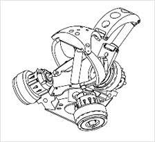
- ProEngineer model
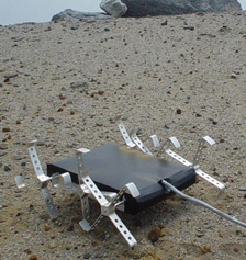
- Experiment at the Canadian Space Agency
Dynamically Reconfigurable Theatre Stage
- This project, involving a mobile theatre stage, was
conceived following an association between the Robotics Laboratory and the
Lantiss (LAboratoire des Nouvelles Technologies de l'Image, du Son et de la
Scène, i.e. LAboratory of New Technologies for Images, Sound and Stages).
The project described herein are part of the first major project of the
Lantiss, involving the design of an electronic castelet (miniature theatre).
This miniature theatre is a model, one tenth of the size of a theatre space,
which is equipped with several technological performance elements including:
motorized lighting, image projection, augmented reality and a deformable
stage. The most important quality of this technological model is to unite
various media within the same tool.
The electronic miniature theatre can be used in two different ways. The miniature theatre can serve as a creation tool, similar to a standard model. The designers can then conceive their theatre productions without having to use an actual theatre hall and all of the equipment in the actual theatre. In this way, they can adjust not only the sets and the movements of the actors, but also the lighting, sound and other technological parameters. The miniature theatre can also be used as a stage on which a production is actually put on for an audience. Thus, miniature theatre productions can be presented with puppets. These productions can be given in front of a small audience or can be filmed and then projected in a large hall.
Mechanically, the mobility of the stage is generated by a multitude of small blocks. These blocks are combined into groups of nine to form modules. By grouping together several modules, one next to the other, one can form a stage. More specifically, the nine blocks of a module are linked together by a parallel mechanism composed of bars and revolute joints. The entire system is actuated by four motors.
The stage of the castelet is made of 12 modules including 9 blocks each (module described before) and 13 modules, mechanically simpler, with only one block. Globally with the 25 modules built, the maximum surface that can be covered is one square meter.
In a more general sense, deformable surfaces developed within this project could also be beneficial for the industrial sector in applications such as molding. Other possible applications include those in the optics field (deformable mirrors), in robotics (complex manipulation) and in the field of simulations, such as terrain simulation for example.
The scientific partners in this project include the Robotics Laboratory, the Computer Vision and Systems Laboratory (CVSL) and the Centre d'Optique Photonique et Laser (COPL), which are all part of the Faculty of Sciences and Engineering at Laval University. The artistic collaborators include the company Ex Machina, the artistic center Avatar, member of the Méduse union, and the theatre research workshop at Laval University. 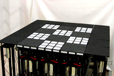
- Dynamically reconfigurable theatre stage
- Description
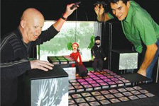
- High-tech puppet show using the miniature stage
Polyhedra with articulated faces
- Consider a
polyhedron as a framework in which the faces are constrained to remain planar.
The resulting construction is referred to here as polyhedron with articulated
faces (PAF). In some cases the PAFs are rigid structures, while in others they
are articulated mechanisms, which possess interesting kinematic properties.
Implementing the planarity constraint mechanically in a framework would be difficult. Instead, it is proposed here to proceed from the outset with a new mechanical construction, which is covered by US patent (No. 7,118,442). First, the faces are built as closed-loop planar linkages using a set of links forming the sides of the polygons. These links are connected by revolute joints at the corners, the axes of the joints being perpendicular to the plane formed by the face. This ensures the planarity of the faces for any configuration. Then, the sides of the faces are connected by revolute joints that lie on the edges of the polyhedron and intersect the joints of the faces at the corner of the faces. Therefore, all the joints associated to a given vertex of the polyhedron intersect at the vertex for any configuration. It is pointed out that the construction of PAFs only require one type of part. Moreover, for PAFs whose edges all have the same length, all the parts are identical.
Mobility
The main interest of the PAFs is their mobility. Some of them are rigid structures while others are articulated mechanisms that deform with nice kinematic properties. Also, some of them are locally mobile but globally rigid. In other words, they can only move in their initial configuration. A kinematic chain with such properties, which is relatively rare, is often called shaky. In order to determine their mobility, i.e. how many degrees of freedom they have, a general method, which involves the first derivative of the constraints equations, is developed. Also, numerical simulations are performed in order to observe the flexed configurations or to find which are shaky PAFs. Finally, plastic models are built. Because of the flexibility of the plastic and the clearance of the joints, the plastic models are more flexible than they should be in theory. As a result, this allows to observe the flexing of the shaky PAFs, which do not significantly move in simulations. It is noted that the range of motion of the plastic models is limited by mechanical interference between adjacent parts. 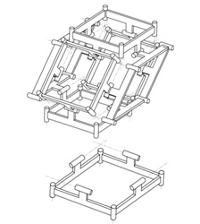
- Construction of a cubic PAF: part, polygon and two configurations of the polyhedron
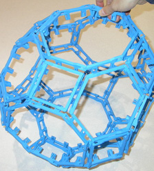
- Great rhombicuboctahedron (26 faces, 72 edges, 48 vertices): mobile (5 DOFS)
- Great rhombicuboctahedron (26 faces, 72 edges, 48 vertices): mobile (5 DOFS)
Accelerometer Arrays
- Accelerometer
arrays are a type of inertial measurement unit that allows the estimation of the
acceleration field of an object, i.e., accelerations of some or all of its
points. Thence, one can infer the trajectory of the object. Because of their
superior accuracy, the vast majority of inertial measurement units resort to
mechanical gyroscopes rather than accelerometers to measure the angular velocity
(angular rates) of an object. Nevertheless, due to their robustness, low cost
and small energy consumption, accelerometer arrays have been preferred to
gyroscope-based inertial measurement units in certain niche applications such as
crashworthiness, projectile guidance and galloping robots.
At the Laval University Robotics Laboratory, research focuses on two aspects of accelerometer arrays: the theory behind accelerometer arrays and their use in human-machine interaction.Theory behind Accelerometer Arrays
In a few words, the work underway at the Laval University Robotics Laboratory is best summarized by the questions it aims at answering:- What accelerometer arrays allow the estimation of what components of a rigid body moving in space?
- What is the minimum number of accelerometers required to estimate the trajectory of an object in space?
- How should accelerometers be positioned and oriented in order to give the best possible accuracy?
- How should we combine the accelerometer estimates in order to obtain robust estimates of the usual kinematics parameters (e.g.: the acceleration of a reference point, the angular acceleration and the angular velocity)?
In order to answer this last question, an accelerometer array was built by Guillaume Fournier and Philippe Gagnon, two students from the Laval University Department of Mechanical Engineering. Because of its octahedral geometry (an octahedron is a polyhedron with eight faces, just like certain dice that are used in board games), this accelerometer array was baptised Octahedral Constellation of Twelve Accelerometers (OCTA). A pair of orthogonal accelerometers (small black boxes on the photograph) is located at each of the vertices of the regular octahedron. Guillaume and Philippe shook this accelerometer array while recording its measurements and those of a reference magnetic sensor that was attached to it (the small gray box on the picture). This latter sensor provided a reference for the six-degree-of-freedom displacements of OCTA. Guillaume and Philippe applied an algorithm developed at the Laval University Robotics Laboratory to extract the angular velocity of OCTA from its accelerometer measurements. They then compared these estimates to those obtained through a time-differentiation of the magnetic displacement sensor estimates. A sample of the obtained results appears in the graph below, where one sees that the estimates computed from accelerometer measurements are close to those obtained from the magnetic displacement sensor (FOB).
In fact, to our knowledge, these are the most accurate angular-velocity estimates obtained from accelerometers ever observed. These results are promising, since accelerometers are less expensive than other sensors used for the measurement of the angular velocity. Well done Guillaume and Philippe!
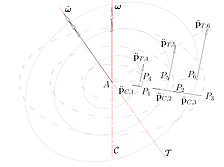
- Representation of the rigid-body acceleration field
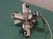
- accelerometer array
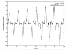
- Angular velocities estimated by the accelerometer array OCTA and by an industrial displacement sensor (FOB)
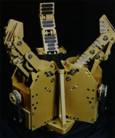
Robot hands: Robust underactuated robotic hand (MARS)
- One of the first
robotic hands developed in the laboratory is the MARS hand (Main Articulé
Robuste Sous-actionnée, i.e. robust underactuated robotic hand). Built in 1996,
it is the result of a collaboration with l'Institut de Recherche en Santé et en
Sécurité du Travail (IRSST), the Institute of health and safe work environments
research. The objective was to design a hand which is both robust and has a
large dexterity so that it can carry out a wide variety of tasks, including
tasks in hostile environments (involving radioactivity, extreme temperatures,
polluted air, etc.).
A prototype of the underactuated 12-DOF robotic hand with 6 actuators was thus built in 1996. The design process involved the use of a CAD software, various simulation programs, and the construction of a cardboard model. The hand is nearly twice the size of the human hand ans weighs 9 kg (20 lbs), yet, its maximum payload is 70 kg (155 lbs.). The hand is actuated by three brushless DC motors for the closing/opening of the fingers and three DC motors for orienting the fingers. The hand is capable of performing cylindrical, spherical and planar grasps with both power and precision grips. The prototype is capable of large enough forces to perform common industrial tasks. It is also equipped with tactile sensors.
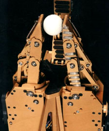
The design of the robotic hand is protected by US patents (US 5,762,390) and a Canadian patent (CA 2 209 863 AA). Robot hands: Underactuated robotic hand for the Canadarm (SARAH)
- Highly
Underactuated 10-DOF Robotic Hand (for the Canadarm)
The robotic hands developed in the laboratory up to this point, had an underactuation only in the fingers. Each finger was thus actuated by its own motor. In 1998 the company MDA Space Missions (previously SPAR Aerospace) contacted the laboratory in order to request the development of a hand for the well-known Canadarm. One of the specifications requested for this new hand was that it should be actuated by only two motors.
This led to the principle of a hand featuring under actuation among the fingers; the opening and closing of the fingers is controlled by only one motor. In fact, one motor is sufficient since it is not necessary for all three fingers to close independently, because all fingers will close to grasp an object as firmly as possible. If one finger is firmly wrapped around an object, the other fingers will continue to close until all fingers are firmly closed. The underactuation among the fingers is achieved through an innovative gear differential mechanism. A second motor allows the orientation of the fingers to be changed to achieve cylindrical, spherical and planar grasps.
A prototype of the highly underactuated self-adaptive 10-DOF robotic hand with 2 actuators was built in 1999. The new hand, SARAH (Self Adaptive Robotic Auxilary Hand), is slightly smaller and weighs only half as much as its 12-DOF predecessor (MARS Hand). It has the same mobility, but is actuated by only two motors.
The SARAH hand was built in collaboration with the Canadian Space Agency. Its design is covered by a US patent (No. 6,505,870) as well as by a pending WIPO patent. The current version is adapted as an end-effector to the SPDM of the Canadian Space Arm for the International Space Station. Robot hands: Robotic hand for the cleaning of nuclear sites
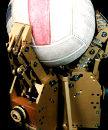
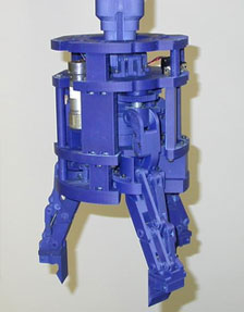
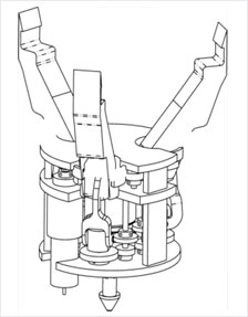
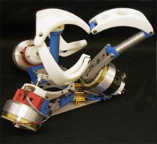
- In 2005-2006, the
Robotics Laboratory has been working on the development of a robotic hand for
the United Kingdom Atomic Energy Authority (UKAEA). The main business of UKAEA
is the clean-up of nuclear sites. One of their tasks is to retreive radio-active
waste from old storing sites in order to package and store it in safer
conditions. The retrieval of the waste is a timely and complex task. The waste
is composed of cans and a variety of debris. Presently, several grippers are
used, each one being adapted to a specific type of object. Unfortunately, the
changeout of the grippers is time consuming. The use of a more flexible gripper
that will replace several specialized grippers will facilitate and accelerate
the retrieval process.
This flexible gripper is adapted from the SARAH hand, which was developed by the Robotics Laboratory and originally designed for use in space. The SARAH hand includes three underactuated and orientable fingers, driven by only two motors. In order to satisfy the requirements of the waste retieval tasks, several components were redesigned. Among others, the new gripper has a significantly larger payload and is adapted to a nuclear environment. Also, the tip of the fingers is designed to grasp cans located in confined spaces, and are yet still capable of handling a variety objects. A plastic prototype of the new gripper (shown above) was built and tested successfully.
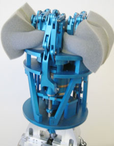
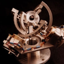
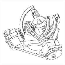
Parallel Mechanisms: The Agile Eye
- The Agile Eye is a
3-DOF 3-RRR spherical parallel manipulator developed for the rapid orientation
of a camera. Its mechanical architecture leads to high velocities and
accelerations. First, the kinematic model of this manipulator was developed.
Then, a geometric optimization was carried out in order to determine the
dimensional parameters which would produce the best accuracy for the mechanism.
A complete dynamic model was then established. Finally, a prototype was designed
and built, and a high-performance controller based on a DSP was developed. The
prototype was built in 1993 and has been gaining in popularity ever since.
The workspace of the Agile Eye is superior to that of the human eye. The miniature camera attached to the end-effector can be pointed in a cone of vision of 140° with ±30° in torsion. Moreover, due to its low inertia and its inherent stiffness, the mechanism can achieve angular velocities above 1000 °/sec and angular accelerations greater than 20000 °/sec2 which is beyond the capabilities of the human eye.
One of the most interesting topics of research related to the Agile Eye is the analysis of its singularities. Surprisingly, the singularity loci of the Agile Eye are independent from the chosen branch (there are a total of 8 branches). Note that for general 3-RRR spherical parallel manipulators, the singularity loci are strictly dependent on the chosen branch. In addition, in the Agile Eye, there exist four poses for the mobile platform in which arbitrary finite motions of the actuators do not produce any output at the mobile platform. Finally, the direct kinematic problem of the Agile Eye allows 8 assembly modes. Parallel Mechanisms: Flight simulator
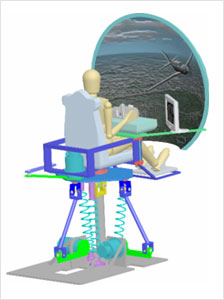
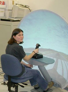
- The area of motion
simulation, especially that of flight simulators (Figure 1), is currently the
main commercial application of parallel mechanisms. These simulators, albeit
very popular and providing very realistic cues, have several notable
disadvantages including a restricted workspace (mainly with respect to
rotation), prohibitive cost, limited operation and they require high
maintenance. Moreover, the oils contained in the actuators can be an
environmental problem for some people.
To eliminate these disadvantages, the laboratory has designed a low-cost flight simulator having a limited number of degrees of freedom and a simple architecture, which is able to create motion cues realistic enough to allow it to be used for the training of pilots (during the first phases of their training).
Several research studies were carried out during this project, including a comparison of cues which can be created by various 3-DOF architectures so as to choose the most suitable architecture. Then, a design of a mechanism was achieved incorporating several innovative ideas, such as static balancing and the use of rotoid electric actuators.The model has 2 legs, of types RRU and RUS, and one passive Hooke joint on which the seat, controls and screen are mounted. The legs allow rotations to be carried out around a cone, while a motor added to the platform allows the platform to pivot in a plane normal to it. Thus a range of motion of ±60 degrees is possible.
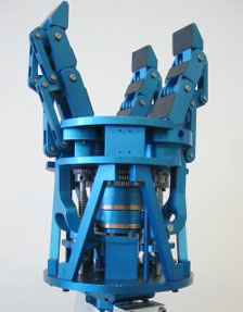
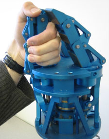
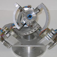
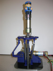
Parallel Mechanisms: SHaDe (a spherical 3-DOF haptic device)
- A 3-DOF haptic
device, called SHaDe, an acronym standing for Spherical Haptic Device, was
developed in our laboratory to allow a human operator to control motions while
being subjected to force feedback. The mechanism presents the particularity of
having only three degrees of freedom, leading to a simpler design and a more
ergonomic utilization. Moreover, the use of a spherical geometry in this haptic
device offers several advantages, namely, a pure rotation around a point located
inside the user's hand (no translations at this point), a large workspace, a
comfortable use, and precise manipulation while the arm is resting.
The prototype makes use of a particular design in which only revolute joints are used, based on a spherical geometry. Indeed, it is a spherical parallel mechanism with two spherical linkage chains of type RRR and one chain of type RRRR. Kinematically, however, the parallel mechanism is equivalent to a spherical 3-RRR one. The RRR(RR) chain was used in order to minimize the link interferences. In SHaDe, all joint axes, passive and active, intersect at a common point which is the center of rotation of the end effector. Such a spherical geometry has also been used in the design of the high-performance camera orienting device, referred to as the Agile Eye.
Numerical analysis was used to optimize the prototype's characteristics with respect to given performance criteria. To this end, a weighted combination of indices was used, including the size of the workspace, the minimal dexterity, the average dexterity, etc. The prototype was built using a Fused Deposition Modeling (FDM) rapid prototyping machine using a commercially available CAD package.
The force control involves an intelligent multi-axis force sensor communicating at a high speed through a serial link with the sensor control sub-program. This sub-program is in turn communicating with the motor torque control and running under QNX, a real-time micro-kernel operating system. Different control laws were created to simulate a robot arm's behaviour or distant hazardous environments. The force control itself is based upon a classical PID scheme enhanced with static compensation plus a feedforward term in order to improve the performance. Tripteron and Quadrupteron robots
- Tripteron
Theoretical research often leads to fascinating discoveries: in this case the tripteron, a 3-DOF translational parallel mechanism. The prototype was first developed through mathematical derivations (systematic type synthesis) based on screw theory. This unique and patented robot enables linear displacements in all directions. It is in fact equivalent to serial Cartesian robots. But since it is a parallel robot, it offers numerous other advantages, including the positioning of its actuators on the base, which reduces the moving inertia and thus allows rapid movements.
Moreover, the tripteron has very simple kinematics, which are actually the same as those of serial Cartesian robots. Also, this robot is isotropic and fully decoupled, i.e. each of the actuators is controlling one Cartesian degree of freedom, independently from the others. This robot thus has no singularities within its workspace and its dexterity is always optimal.
The figures below also indicate that it is possible to orient the linear actuators in different directions, for example in a parallel or co-planar manner rather than orthogonally. The prototype developed in our laboratory is of the type 3-PRRR.
Quadrupteron
Akin to the tripteron, the quadrupteron was also developed through systematic type synthesis. Ressembling the tripteron on many ways, the unique feature of the quadrupteron is mainly its 4 DOFs. In addition to the three translations, one rotation along the vertical axis is possible. The prototype thus has three legs of the type PRRU and one leg of type PRRR.
The quadupteron reproduces the same movements, although with an increased dexterity, as the well-known SCARA robot (Selective Compliant Assembly Robot Arm), i.e., the Schönflies motions. The quadrupteron is isotropic in translation. The singularities are only present in two orientations, ±90 degrees, which cannot be reached since the workspace is ±60 degrees (which is already very attractive).
The design of the prototype was achieved through a variety of studies in order to reduce the presence and size of the singularities and to optimize the deterity and workspace.