Navigation : EXPO21XX > ROBOTICS 21XX >
H24: Underwater Robots Research
> Cornell University - CUAUV
Cornell University - CUAUV

Videos
Loading the player ...
- Offer Profile
- The Cornell University Autonomous Underwater Vehicle (CUAUV) team designs and builds AUVs for competition and research. Our team and vehicle have received acclaim and support from industry professionals due to our performance and long-standing tradition of excellence.
Product Portfolio
Vehicles
- Autonomous Underwater Vehicles
Autonomous Underwater Vehicles (AUVs) are robotic submarines. They are a part of the emerging field of autonomous and unmanned vehicles and are primarily used as low cost reconnaissance tools. AUVs are valued for both their expendability and replaceability; they can be deployed in hazardous environments without risking human divers. Economically, the potential for cheap scalability make AUVs ideal for large scale and long term data collection tasks.
AUVs today are used within three main fields: military, offshore industry, and university research. The U.S. military and Department of Homeland Security are interested in using AUVs for mine detection, harbor patrol, and counter-surveillance. The offshore industry uses AUVs for equipment inspection and sea floor profiling for oil surveying. University researchers often use AUVs to facilitate specific research projects which require the autonomy and range that only AUVs can offer. For delicate data gathering tasks like wild-life monitoring and water profiling, AUVs are the only way to collect large sets of sample data consistently over time, due to their relatively small size and inconspicuous nature.
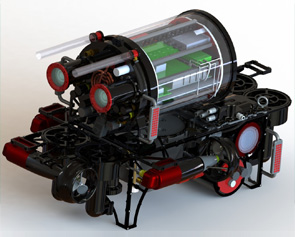
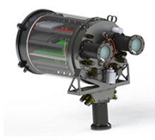
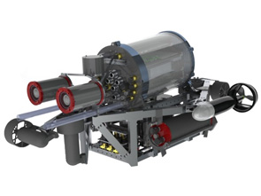
Killick: 2012 Competition/Research Vehicle
- Killick is the CUAUV 2011-2012 vehicle, a joint
competition and research vehicle. The design focuses on reducing the size
and weight of the vehicle platform while maintaining full competition
capabilities and control properties. The main improvements include stronger
frame structures and pressure vessels, a streamlined electronics system,
improved sensor suite, and improved vision algorithms.
Key stats:- Depth rating: 50 ft (acrylic hull), 250 ft (aluminum hull)
- Max speed: 1.4 Knots
- Weight: 75 lbs
- Overall Dimensions: 31" L x 21" W x 19" H
- Run time: 1.5 hours
- Doppler Velocity Log
- Temperature sensor
- Custom-built hydrophones
- AVT Guppy downward camera
- AVT Guppy forward camera
- Custom-built IMU
- 3DM-GX1 IMU
- Depth sensor
- Internal pressure sensor
- Sparton GEDC-6 Gyro-Enhanced Digital Compass
- Cantilever rack system
- Integrated cameras
- Compact form factor
- Both Ethernet and Fiber Optic tethers
- Reliable power system
- Hot swappable battery pods
- Strafing thrusters
- Redundant main sealing system
- Wet-mate tether
- SEACON underwater connectors
- Plug and Play serial
- Vacuum-sealed hull

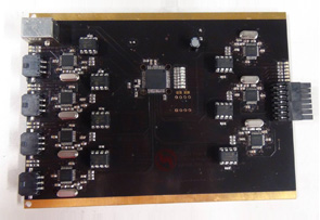
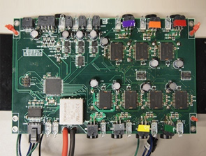
Killick's Electrical Infrastructure
- Killick's electrical system contains all power and
serial infrastructure for the vehicle's actuators, sensors, and computer.
One of the largest changes this year was made across the entire electrical infrastructure. To reduce wire routing required inside the vehicle, all boards with lines leaving the main hull are connected via blind-mate Molex connectors. This easily halved the number of wires in the vehicle, and make routine electrical maintainence much easier.
All boards save the computer were designed and populated by team members. 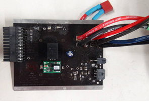
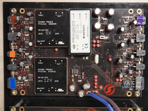
Power System
- Killick's power system takes power from the battery pods and converts it into regulated voltage for the sensors and computer. It provides isolated 5V, 12V, and 24V rails for various sensors and boards on the vehicle.
Mechatronics System
- The mechatronics system includes all the electrical infrastructure that drives the thrusters, torpedo launchers, marker droppers and grabber. It also interfaces with the switchbox, giving the software access to the mission-start button and the kill circuitry.
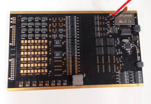
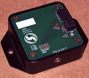
Sensor Control System
- The sensor control system includes the infrastructure to
control Killick's various sensors as well as the communication used between
the sensors and the computer. This includes a general purpose Input/Output (GPIO)
board for simple sensor interface, and a serial board for providing easy
communicatoin between the boards, the more complex sensors, and the CPU.
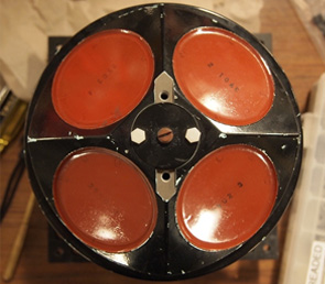
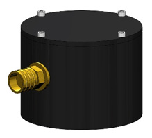
Custom Passive acoustic sensor
- The hydrophones are a passive acoustic system that use
four Reson TC4013 elements and an Analog Devices SHARK-21369 to determine
the relative direction to an underwater pinger. They are capable of
discriminating between multiple pingers of different frequencies operating
simultaneously and listening to only the one at the selected frequency.
They can operate in the 20-35 kHz range. This year, a board to implement active acoustic elements has been developed, but still requires further testing.
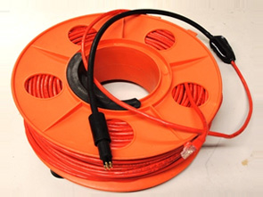
Tethers
- To communicate with the shore, Killick has an Ethernet tether for on-line testing.
Computer and Memory
- Killick's onboard computer is comprised of an Intel Core I7-2710QE quad core processor on a mini-ITX motherboard, 4GB of RAM, and an Intel X25-E Extreme 32GB solid state drive. This provides more than enough computing power for all mission, machine vision, and control processing tasks. A PCI Express expansion card is used to provide 3 IEEE1394 ports for the vehicle's cameras. The computer runs a minimalist installation of Debian GNU/Linux. Communication with all external sensor and actuator boards is routed through a custom serial interface board.
Killick's Sensors
- In order to complete its mission, Killick uses a wide array of sensors for vehicle control and environmental sensing, including a Dopper Velocty Log, two compasses, a depth sensor, two IMUs, and two cameras.
Doppler Velocity Log
- The RDI Workhorse Navigator DVL gives position and enables closed-loop velocity control. The DVL provides velocity data in all three dimensions, and also features a built in temperature sensor, compass, and altitude sensor.
Orientation Sensor
- A Microstrain 3DM-GX1 Orientation Sensor provides the vehicle's heading, pitch, roll and velocity rates in 3D space. This data is used in the Kalman filter of the controller to allow for better sensor fusion and faster control response
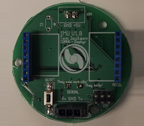
Custom IMU
- The Inertial Measurement Unit (IMU) measures the roll, pitch, and yaw velocities, as well as the x,y, and z acceleration. It also has an adjustable filter on the microcontroller to filter the data. The data is automatically updated and is sent to the computer using an RS-232 communication line.

Cameras
- Killick uses three cameras, two forward facing and one
downward facing.
Two AVT Guppy F-080C Color CCD Cameras are used for the vehicle's forward vision. An An AVT Guppy F-046 Color CCD Camera is used for the vehicle's downward vision.

Depth Sensor
- Analog pressure data (up to 100 PSI, or approximately 55 meters below the surface) is obtained from an MSI UltraStable-300 pressure transducer, operating in a 4-20 mA current loop.
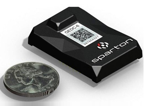
Sparton Compass
- A Sparton GEDC-6 Compass also provides the vehicle's heading, pitch, roll and velocity rates in 3D space. It also provides the vehicle's heading with magnetometers compensated by accelerometers and gyroscopes.
Killick's Mechanical Infrastructure
- The mechanical systems consist of the vehicle structure, upper hull, actuators, and external enclosure subsystems. These are responsible for keeping electronic components sealed, and provide mounting points and protection for all of the sensors and enclosures. All custom mechanical components were developed and constructed in-house. Team members designed parts in CAD software (SolidWorks) then validated and optimized their designs using FEA software (ANSYS). Team members fabricated the ultimate design in the Emerson Machine Shop.
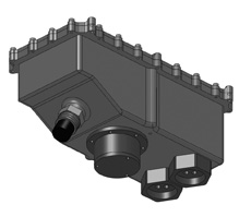
Upper Hull Pressure Vessel
- The Upper Hull Pressure Vessel (UHPV) protects and supports all of the serial, power, and sensor interface boards for Killick. It also houses the computer and actuator control system. The UHPV also serves as the interface between the internal boards and external devices.
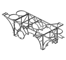
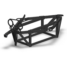
Vehicle Frame
- The vehicle frame supports and contains mounting points for the pressure vessels, actuators, and sensors. The frame is constructed of CNC-machined aluminum sheet and is designed to minimize weight and size.
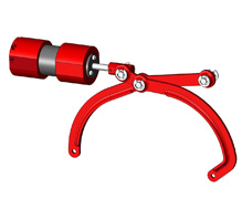
Actuators
- Killick utilizes a number of custom and COTS electo-mechanical components to dynamically interact with its surroundings. The commercial thrusters give five degrees of freedom, and a custom pneumatics system accomplishes the mission tasks.
External Enclosures
- Killick’s external pressure vessels contain various electrical systems outside of the upper hull pressure vessel. These waterproof vessels isolate the systems from unwanted noise and allow for flexibility in the configuration of the vehicle. Systems contained in external pressure vessels include the hydrophones passive acoustic system and switchbox.
Killick Software
- All of Killick's higher level functionality, including completing mission tasks, is acheived through the vehicle’s software system. The software stack is built upon the Debian GNU/Linux operating system and includes custom shared memory, serial daemon, multithreaded vision, control, and mission systems. All custom software is written in C/C++ and Python.
- Shared Memory
The shared memory system allows simultaneous access to global variables throughout the vehicle's software infrastructure. These variables are also synchronized across various boards through a standardized serial protocol, allowing for easy reading and writing. - Logging
Killick's logging system captures the state of the vehicle during mission runs. This allows the software team to do offline review and testing on the vehicle and captures rare software bugs. - Control
The control system provides Killick with the ability to combine sensor data into a reliable vehicle state and use this knowledge to control the thrusters and actuators. - Vision
Killick's vision-processing system is designed to give the vehicle up-to-date and accurate data about the surrounding mission elements. - Mission Planner
The mission planner, written in Python, allows for high level missions to be written written in a simplistic and abstracted manner. - Real-Time Data Display and Visualizations
Key to improving the vehicle's performance is understanding what it is doing, so we have developed utilities to display and visualize the vehicle state. - Simulator
The simulator allows for the testing of missions in a virtual environment. This helps us verify the correctness of missions before testing them on the vehicle, saving time. - HTTP Diagnostic Interface
The HTTP Diagnostic Inteface, also known as the Web GUI, allows for control of basic vehicle functions through a web browser. - Navigation and Mission Element Localization
This year software was developed to help localize objects on the course. The localization code generates a probability map on the location of an object given the vision received.
- Shared Memory
Vehicles
- Autonomous Underwater Vehicles
Autonomous Underwater Vehicles (AUVs) are robotic submarines. They are a part of the emerging field of autonomous and unmanned vehicles and are primarily used as low cost reconnaissance tools. AUVs are valued for both their expendability and replaceability; they can be deployed in hazardous environments without risking human divers. Economically, the potential for cheap scalability make AUVs ideal for large scale and long term data collection tasks.
AUVs today are used within three main fields: military, offshore industry, and university research. The U.S. military and Department of Homeland Security are interested in using AUVs for mine detection, harbor patrol, and counter-surveillance. The offshore industry uses AUVs for equipment inspection and sea floor profiling for oil surveying. University researchers often use AUVs to facilitate specific research projects which require the autonomy and range that only AUVs can offer. For delicate data gathering tasks like wild-life monitoring and water profiling, AUVs are the only way to collect large sets of sample data consistently over time, due to their relatively small size and inconspicuous nature.
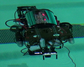
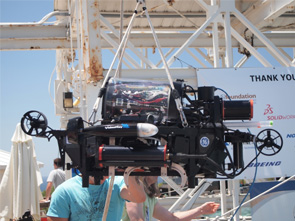
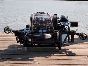
Drekar: 2011 Competition/Research Vehicle
- Drekar is the CUAUV 2010-2011 vehicle, a joint
competition and research vehicle. The design focuses on reducing the size
and weight of the vehicle platform while maintaining full competition
capabilities and control properties. The main improvements include stronger
frame structures and pressure vessels, a streamlined electronics system,
improved sensor suite, and improved vision algorithms.
Key stats:- Depth rating: 100 ft (theoretical)
- Max speed: 1.4 Knots
- Weight: 85 lbs
- Overall Dimensions: 42" L x 28" W x 20" H
- Run time: 1.5 hours
- Doppler Velocity Log
- Temperature sensor
- Custom-built hydrophones
- AVT Guppy downward camera
- AVT Guppy forward camera
- Custom-built IMU
- 3DM-GX1 IMU
- Depth sensor
- Cantilever rack system
- External cameras
- Expandable payload
- Custom underwater connectors
- Both Ethernet and Fiber Optic tethers
- Reliable power system
- Hot swappable battery pods
- Strafing thrusters
- Reliable sealing system
- Wet-mate tether
- SEACON underwater connectors
- Plug and Play serial
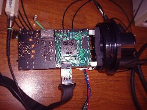
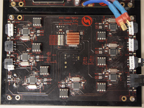
Drekar Electrical Infrastructure
- Drekar's electrical system contains all power and serial infrastructure to support the vehicle's sensors, actuators, and computer. All boards in the power, serial, sensor control and actuator control subsystems were designed and populated by team members.
Power System
- Drekar's power system takes power from the battery pods
and converts it into regulated voltage for the sensors and the computer. It
provides 5V, 12V and 24V at different points.
Mechatronics System
- The mechatronics system includes all the electrical infrastructure that drives all thrusters, torpedo launchers, marker droppers, grabber, and the switchbox.
Sensor Control System
- This system includes the infrastructure to support Drekar's various sensors as well as the serial communication used between sensors and the computer. The General Purpose Input/Output (GPIO) board and a serial board are used for this.
Custom Passive acoustic sensor
- The hydrophones are a passive acoustic system that uses four Reson TC4013 elements and an Analog Devices SHARC-21369 to determine the relative direction to an underwater pinger. They are capable of discriminating between multiple pingers of different frequencies operating simultaneously and listening to only the one at the selected frequency. They can operate in the 20-35 kHz range. The electrical system for the passive acoustic system is entirely new this year.
Tethers
- To communicate with the shore, Drekar has both an Ethernet tether and a fiber optic tether for when greater distance from the control is needed, as in long range search missions.
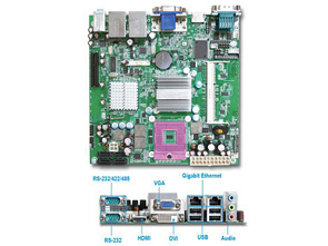
Computer and Memory
- Drekar's onboard computer is comprised of a Portwell WADE-8067 low power embedded Mini-ITX motherboard, an Intel Core 2 Extreme QX9300 quad core processor, 4GB of RAM, and an Intel X25-E Extreme 32GB solid state drive. This provides more than enough computing power for all mission, machine vision, and control processing tasks. A PCI Express expansion card is used to provide 3 IEEE1394 ports for the vehicle's cameras. The computer runs a minimalist installation of Debian GNU/Linux. Communication with all external sensor and actuator boards is routed through a custom serial interface board.
Sensors
- In order to complete its mission, Drekar uses a wide array of sensors for vehicle control and environmental sensing, including a Dopper Velocty Log, two compasses, a depth sensor, two IMUs, and two cameras.
Doppler Velocity Log
- The RDI Workhorse Navigator DVL gives position and enables closed-loop velocity control. The DVL provides velocity data in all three dimensions, and also features a built in temperature sensor, compass, and altitude sensor.
Orientation Sensor
- A Microstrain 3DM-GX1 Orientation Sensor provides the vehicle's heading, pitch, roll and velocity rates in 3D space. This data is used in the Kalman filter of the controller to allow for better sensor fusion and faster control response
Custom IMU
- The Inertial Measurement Unit (IMU) measures the roll, pitch, and yaw velocities, as well as the x,y, and z acceleration. It also has an adjustable filter on the microcontroller to filter the data. The data is automatically updated and is sent to the computer using an RS-232 communication line.
Cameras
- Drekar uses two cameras, one forward facing and one
downward facing.
An AVT Guppy F-080C Color CCD Camera is used for the vehicle's forward vision. An An AVT Guppy F-046 Color CCD Camera is used for the vehicle's downward vision.
Depth Sensor
- Analog pressure data (up to 100 PSI, or approximately 55
meters below the surface) is obtained from an MSI UltraStable-300 pressure
transducer, operating in a 4-20 mA current loop.
Drekar Mechanical Infrastructure
- The mechanical systems consist of the vehicle structure, upper hull, actuators, and external enclosure subsystems. These are responsible for keeping electronic components sealed, and provide mounting points and protection for all of the sensors and enclosures. All custom mechanical parts were designed in CAD software (SolidWorks) and machined by team members .

Upper Hull Pressure Vessel
- The Upper Hull Pressure Vessel (UHPV) protects and supports all of the serial, power, and sensors infrastructure for Drekar. It contains the computer and actuator control infrastructure. The UHPV also serves as the interface between the internal boards and the external devices.
Vehicle Frame
- The vehicle frame supports all of the pressure vessels,
actuators, and sensors. The frame is constructed of aluminum box tubes and
is designed to maximize rigidity and compactness.
Actuators
- Drekar utilizes a number of custom and COTS electo-mechanical
components to make the AUV more than a series of (aluminum) tubes. The
commercial thrusters give five degrees of freedom, and custom pneumatics
system accomplishes the mission tasks.
External Enclosures
- Drekar's external pressure vessels contain various electrical systems located necessarily outside of the upper hull pressure vessel. These waterproof vessels isolate the systems from unwanted noise and allow for flexibility in the construction of the vehicle. Systems contained in external pressure vessels include the forward and downward facing AVT Guppy cameras, the hydrophones passive acoustic system, and switchbox.
Drekar Software
- All of Killick's higher level functionality, including completing mission tasks, is acheived through the vehicle’s software system. The software stack is built upon the Debian GNU/Linux operating system and includes custom shared memory, serial daemon, multithreaded vision, control, and mission systems. All custom software is written in C/C++ and Python.
- Shared Memory
The shared memory system allows simultaneous access to global variables throughout the vehicle's software infrastructure. These variables are also synchronized across various boards through a standardized serial protocol, allowing for easy reading and writing. - Control
The control system provides Drekar with the ability to combine sensor data into a reliable vehicle state and use this knowledge to control the thrusters and actuators. - Vision
Drekar's vision-processing system is designed to give the vehicle up-to-date and accurate data about the surrounding mission elements. - Mission Planner
The mission planner, written in Python, allows for high level missions to be written written in a simplistic and abstracted manner. - Real-Time Data Display and Visualizations
Key to improving the vehicle's performance is understanding what it is doing, so we have developed utilities to display and visualize the vehicle state. - Simulator
The simulator allows for the testing of missions in a virtual environment. This helps us verify the correctness of missions before testing them on the vehicle, saving time. - HTTP Diagnostic Interface
The HTTP Diagnostic Inteface, also known as the Web GUI, allows for control of basic vehicle functions through a web browser.
- Shared Memory
CUAUV Activities
- Over the past twelve years, CUAUV has built nine different fully functional Autonomous Underwater Vehicles. For most of this history, vehicle missions were focused entirely around the AUVSI AUV competition. This competition combines visual, acoustic and navigational tasks into an underwater obstacle course that the vehicle must complete autonomously. Recently, CUAUV has also been running missions as a part of the Floating Classroom Project to study Macrophyte growth in Cayuga lake. CUAUV also conducts many volunteer and outreach activities geared at increasing interest in math, science, and engineering in the community.
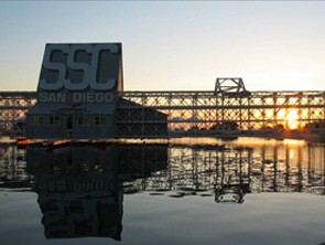
AUVSI/ONR Competition missions
- One of CUAUV’s primary objectives each year is to
successfully complete the competition mission for the Association for
Unmanned Vehicle Systems International (AUVSI). Teams from around the world
compete at this annual event, which takes place each summer at the TRANSDEC
Facility in San Diego, California. Completing the competition requires each
vehicle to autonomously execute a sequence of tasks while remaining fully
submerged. Missions for this competition include visual and acoustic tasks.
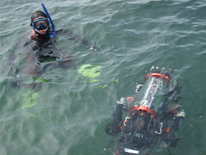
Lake Research
- On the 22nd of October, CUAUV along with a research group from SUNY Cortland, and members of the Ithaca High School Robotics Team boarded the Floating Classroom Project and set course for the mouth of Cayuga Lake. The purpose of our visit was to observe the effectiveness of an herbicide in deterring the spread of Hydrilla, an invasive plant species, to the mouth of Cayuga Lake. The vehicle was deployed in two locations and sent to a maximum depth of 12 meters in order to observe the lake bottom. No Hydrilla was seen from our dives; additionally, it appeared that other plant life remained unaffected by the herbicide. Our vehicle's voyage concluded by inspecting the propeller of the Floating Classroom Project.
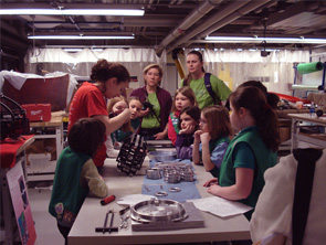
Community Outreach
- In addition to our technical activities and missions, CUAUV also conducts number of outreach programs each year. These programs are a good way to give back to the community and to improve team moral. Some of our outreach activities in the last year include a workshop for 80 junior girl scouts, two 8 week afterschool programs at a local elementary school, a presentation at the Ithaca Sciencenter, and participation in several Diversity Programs in Engineering events.