- Offer Profile
- Bystronic is a leading global provider of high-quality solutions for the sheet metal processing business. The focus lies on the automation of the complete material and data flow of the cutting and bending process chain. Bystronic’s portfolio includes laser cutting systems, press brakes, and associated automation and software solutions. Comprehensive services round off the portfolio.
Laser cutting
-
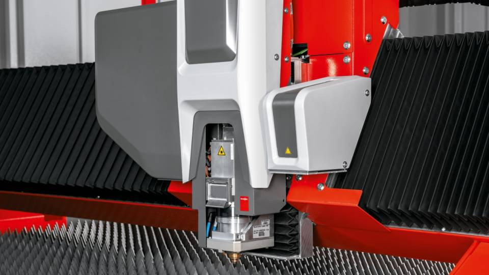
Tap into the full potential of fiber laser technology. Cut steel with up to 30 kW laser power and sheet thicknesses up to 50 mm.
Even as a newcomer to laser cutting, you benefit from performance packages with low investment costs and a wide range of applications. In return, you get low operating costs and low maintenance requirements.Our laser cutting machines are also designed for automation. With the right solution, both unmanned production and a quick switch to manual processing are possible.


ByStar Fiber
-
Maximum productivityFiber laser cutting in the fast lane
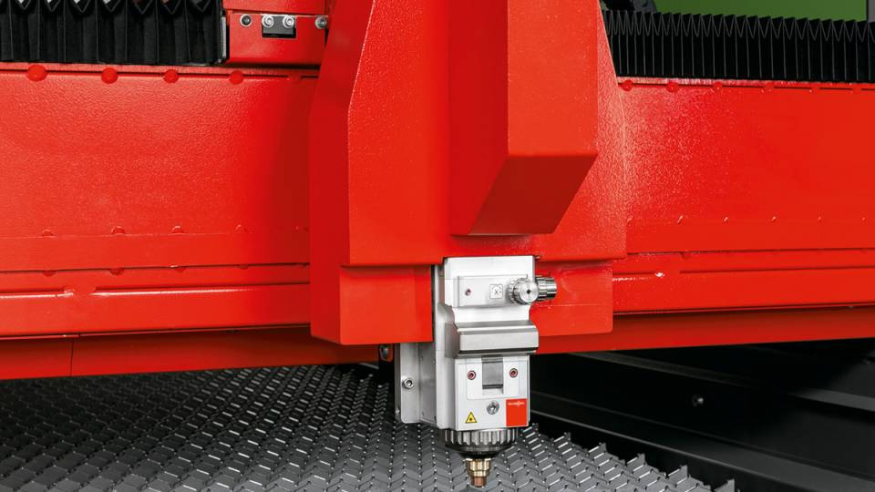
The ByStar Fiber will boost your output and increase your process reliability. With the fiber laser for cutting metal, you are one step ahead of the competition. Take your production to the next level with smart features and more laser power.


ByCut
-
Highest productivity for competitive fiber laser cutting
- Available in models 3015, 4020, 6520, 8020 and 12020. This means that sheet metal up to 12 × 2 meters in format can be processed quickly and economically
- Unparalleled high parts production and first-class cutting quality for thin to medium thick sheet metal, depending on laser power
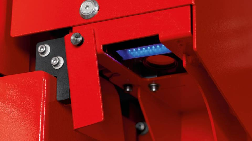
- Additional functions (Power Cut Fiber, Cut Control Fiber, Nozzle Changer, Detection Eye) and automation options increase the application scope to a maximum
- Low operating costs since minimal energy is used and no laser gas is required
- High flexibility. Even non-ferrous metals can be processed with excellent quality
- Available in models 3015, 4020, 6520, 8020 and 12020. This means that sheet metal up to 12 × 2 meters in format can be processed quickly and economically


ByCut Smart
-
Power and precisionFast cutting with no interruptions
Improve your production with our fiber laser machines:
- ByCut Smart 3015 and 4020: The proven sizes. The small and medium models with new laser power of up to 15 kW ensure excellent cutting performance and high part output for thin to medium-thick sheets.
- ByCut Smart 6225: With the use of larger sheets you increase your output with our medium-sized model.
- ByCut Smart 12025: With the XXL fiber laser cutting system with a laser power of up to 15 kW you can process sheets of up to 40.02 x 8.20 feet.


ByCut Eco
-
Robust laser cutting systemFor successful sheet metal processing
The ByCut Eco 3015/4020 offers you everything to get started with laser cutting sheet metal:
- Simplicity
- High performance
- Quality and consistency
- Potential for automation
- An attractive price
As a result, you have more profit per part from the very beginning.


ByStar Fiber
-
Maximum productivityFiber laser cutting in the fast lane
The ByStar Fiber will boost your output and increase your process reliability. With the fiber laser for cutting metal, you are one step ahead of the competition. Take your production to the next level with smart features and more laser power.
The ByStar Fiber is unbelievably fast. With a power of up to 20 kilowatts, you will process your orders with fiber laser cutting in record time.
Speed does not come at the expense of quality – on the contrary: Our high-quality cutting heads are Swiss made and achieve the highest level of quality, even in demanding applications.


Laser Automation
-
Productivity & efficiencyOptimize your laser cutting system with laser automation
Our automation solutions represent the highest power and quality. Rely on a fully automatic sheet loading process with weight control on the lift and monitoring for tilted parts during sheet metal unloading. For reliable and safe automated production.
- ByTower Compact
- ByTower
- Byloader
- ByTrans & ByTrans Extended
- BySort
- ByTrans Modular
Tube laser - Solutions for laser cutting tubes
-
Flexible, powerful, and fastMore efficient cutting processes for greater profit
Our high-end tube laser makes higher accuracy and quality possible in your production. The 2D and 3D laser cutting technology takes care of it. Process a variety of materials and sizes with precision. And in doing so, save energy and maintenance costs.

ByTube Star 130
-
Increase qualityFast and flexible tube laser cutting
Accelerate the laser cutting of tubes and profiles with the ByTube Star 130. Tube laser cutting with our high-end tube laser boosts the quality and performance in your production through:
- Highest precision
- Ease of use
- Fully automatic setup of all profiles, including open and elliptical tubes

FL 170
-
Fast cutting processes boost your profits
The FL 170 fiber laser combines the benefits of a fiber laser with the versatility of 3D cutting. The cutting spectrum can be extended to open sections, such as beams, angles and channels. The FL 170 3D tube laser cutting machine excels thanks to its low power consumption and low maintenance requirements.
A wide range of tubes with circular, square, and rectangular geometries as well as open sections are precisely machined using 2D and 3D laser cutting technology. 3D tube laser cutting at angles of up to 45 degrees, as preparation for the welding process, is also possible. Thanks to tube laser cutting, there is no need for time-consuming milling, drilling, or sawing.

FL 300
-
Unlimited possibilities Processing pipes up to 12.5 m in length
The FL 300 is suitable for various materials and diameters. As a versatile steel cutting tool, the laser tube cutting machine has a lot to offer:
- Process pipes up to 12.5 m
- Cut parts up to 12.2 m
- Linear load capacity of 60 kg/m, allowing the CO2 laser to efficiently cut thick materials
Press brakes
-
Smart, intuitive & powerfulPress brakes for all needs
With bending technology from Bystronic, there is something for everyone - from carefree packages for beginners to high-performance press brakes for complex bending processes.
Our machines are easy to operate. The intuitive software simplifies all process steps and ensures convenient bending even without prior knowledge. In combination with our automation solutions, automatic production is possible at any time.

XPert Pro
-
Bending technology for highest demands on process speed and flexibility
- Maximum flexibility and performance. Various configurations and a comprehensive range of performance options for every requirement and field of bending application
- Consistently high bending quality. The Xpert Pro’s dynamic crowning and patented pressure reference technology offer bending with maximum repetition accuracy
- Precision from the very first part. Intelligent assistant functions, such as the material curve generator and the LAMS angle measuring system, guarantee bending results with the highest precision while requiring only very few operating steps
- Highest degree of operating convenience and transparent process control thanks to the intuitive ByVision Bending user interface. A touch screen provides all the information required for the fast processing both of individual orders and extensive order lists
- Convenient offline programming of bending jobs. Subsequently, simple data import in ByVision Bending without interrupting the running production process
- Maximum flexibility and performance. Various configurations and a comprehensive range of performance options for every requirement and field of bending application

ByBend Star 120
-
Metal press brake with powerThe compact bending miracle
Make use of the space in your production. The ByBend Star 120 is a metal press brake with minimal space requirements. It offers you bending technology for the highest demands in:
- Process speed
- Flexibility
- Accuracy
It is just right when applications are too big for a "small" machine and too small for a "big" machine.

ByBend Star 40 & 80
-
Our mobile bending machinesAlways ready for action & up to 25 mm/second fast
With the two ByBend Star bending machine models 40 and 80 you can bend small and medium-sized parts more economically than ever before. You benefit from the mobile use of the bending machines to the convenient handling. The compact chassis enables bending speeds of up to 25 millimeters per second.
Bystronic has done pioneering work with the ByBend Star 40 and 80. They are the first bending machines for mobile use. They are quickly ready for operation in the tightest of spaces and ensure the highest bending quality at all times. With less than 6 square meters of space needed, they are almost as compact and flexible as a Swiss army knife.

ByBend Smart E
-
With the ByBend Smart E you achieve a new dimension in bending - electric instead of hydraulic is the name of the solution. Benefit from:
- Higher speed
- Cleaner production
- Lower expenses
- Automation readiness
Thanks to the high performance, you have a faster cycle time in your production - which means increased productivity. At the same time, you reduce energy consumption with the intelligent electrical design of the press brake.

ByBend Smart
-
High potentialFast, precise, with smart options
The press brake machine, ByBend Smart, offers you the crucial plus in bending technology:
- Speed
- Precision, and
- Numerous smart options
The ByBend Smart offers you new perspectives and guarantees the highest flexibility at attractive terms. The simple operation enables a successful entry into bending technology.

Xpress
-
PressbrakeBundled technology for newcomers
Are you looking for a simple way to get started in bending? The Xpress makes the first steps easy and offers high-value bending technology at an attractive price. It is therefore also affordable for very small businesses.
Bending is not an art – at least not with the Xpress, our worry-free package for newcomers. By concentrating on the essentials, users become professionals in air bending and coining in no time. The intuitive BySoft Cell Control Bend software also makes everyday bending easier and supports you at every step.

Xpert 250-1000
-
Highest qualitySheet metal bending with maximum performance
With our Xpert 250-1000, you can bend larger and more extreme applications than ever. And the quality is right – from the first to the last part.
The Xpert 250-1000 ensures the highest performance – even with complex bending processes and varying materials of different thicknesses and quality. You thus process your orders faster and with greater flexibility.

Modular Tool Changer
-
Accelerate set-up timesBend faster thanks to an automatic tool change
Don't waste any more time: Set-up takes up to 70% of the bending process. It is time consuming and physically demanding for large tools.
The Modular Tool Changer takes a load off your personnel and boosts your productivity. It changes tools on your Xpert Pro press brake fully automatically, thereby ensuring high-precision bending processes.

Mobile Bending Cell
-
Accelerate set-up timesBend faster thanks to an automatic tool change
Don't waste any more time: Set-up takes up to 70% of the bending process. It is time consuming and physically demanding for large tools.
The Modular Tool Changer takes a load off your personnel and boosts your productivity. It changes tools on your Xpert Pro press brake fully automatically, thereby ensuring high-precision bending processes.

Bending Cell
-
Work autonomouslyFully automatic bending – 24/7
With our automatic sheet metal bending machine, your production runs at full speed: In a team with an agile robot, our high-end Xpert Pro press brake works completely autonomously.
- The robot and press brake can be controlled intuitively and conveniently via the touchscreen.
- The intelligent BySoft Cell Control Bend software independently creates optimal bending sequences.
The software also determines the appropriate tools for each job list.
BySoft Suite

-
Do you want more integrated and transparent process management in your sheet metal business? Would you like to respond to the needs of your customers faster and more accurately? If yes, we have a solution for you: our BySoft Suite.
The future lies in interoperability.
Benefit from a complete ecosystem. With our powerful BySoft Suite, you can interconnect different levels:
- in your own company
- at your suppliers
- at your customers
The result: you optimize your supply chain and provide a better service for your customers.
Smart Factory

-
Bystronic Smart Factory
Prepared for industry 4.0 thanks to networking
Start optimizing your manufacturing processes today with a view to digital production:
- top-of-the-range machines
- automated production cells
- the fully integrated Smart Factory of tomorrow
With Bystronic, this is accomplished step by step. Because: Our scalable solutions grow with your requirements.