
- Offer Profile
- MIT biomimetic robotics lab aspires to build a mutidisciplinary foundation of hyperdynamic robotics. Hyperdynamic robotics involves dynamic modeling, hierarchical control architecture, monolithic multi-material manufacturing, novel actuation technologies, and morphological design tool that enable the development of high performance dynamic robotic platforms.
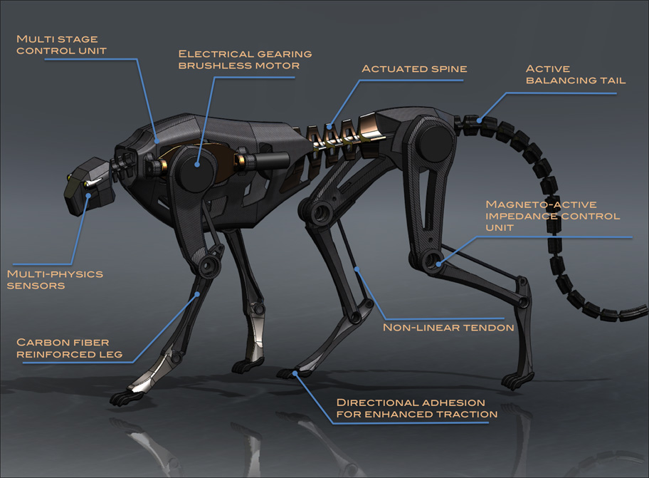
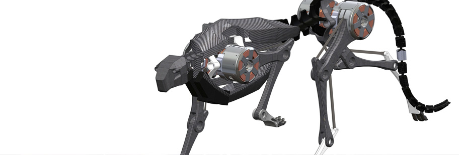
Cheetah inspired quadruped robot - High-speed locomotion platform
Stickybot
- Stickybot is a quadruped robot capable of climbing
smooth surfaces, such as glass, acrylic and whiteboard using directional
adhesive. The design is mostly inspired by morphologic study of the best
climber, Gecko lizard. The robot is operated by 12 servo motors controlled
by PIC controller with force sensors. Stickybot is the incarnation of
biomimetic design constituents that I invented, including underactuated
hierarchical system, cable driven actuation and passive compliance-based
force control scheme. I initiated and designed this robot for testing of
synthetic gecko dry adhesion April 2005. After an year's furious effort on
foot design, push-pull cable actuation mechanism, Stickybot succeeded to
climb glass surface reliably.
Adhesion system model (What is stickiness?)
Many people asked me about what kind of material the sticky pads made out of and there is a large spectrum of surface energy. As I learned more about molecular mechanics, however, it is getting more convincing to me that adhesion is depends more on geometry of structures than the type of material. In the beginning of RiSE (Robots in Scansorial Environment) project, winter of 2003, I was wondering about the mechanism why sticky stuff stick on surfaces. What feature makes things sticky? My hypothesis was that the more compliant the structure of a system, the stickier it is. 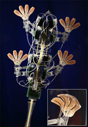
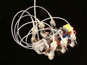
Stickybot
- Quadruped robot capable of climbing smooth surfaces, such as glass, acrylic and whiteboard using directional adhesive.
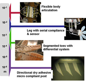
Hierarchical compliance system
- As mentioned in adhesion model, surface conformation is
essential in adhesion since Van der Waals force is very weak unless there is
intimate contact between two surfaces. Van der Waals force is known to be
very weak, although its usage is ubiquitous in our life. Most common example
is conventional tape that uses very soft material for compliance. Vertical
climbing on various surfaces requires more sophisticated system than single
thin layer of soft polymer used in tape. In natural and artificial
environment, roughness in many length scale is presented. Thus, in order to
maximize the number of molecules in intimate contact between feet and wall
surfaces, corresponding length scale compliance is needed. Gekco species
also present hierarchical compliance in their body. Flexible body and leg
can conform at the centimeter scale. Toes and soft skin are responsible for
1~2 millimeter scale. Within a millimeter scale, specialized hair structures
are composed of lamellae, setae and nano scale spatulae covering up to
nanometer scale. Stickybot inherits similar characteristic comprising 12
active actuator, 8 DOF serial and 4 passive compliant DOFs in leg and 16
segmented toes controlled via two stage differential cable driven system.
Directional adhesion
The most extraordinary feature of Stickybot is Directional adhesive. Climbing robot are not It has Anisotropic structure featured controllable adhesion with directionality in adhesion force. The movie clip above demonstrates directional adhesion compared to conventional double sided tape. Unlike conventional tape, it sticks on smooth surface with very small preload and is also able to detach with by reducing load. If it is loaded in desired direction, it creates maximum contact minimizing stress concentration along the contact area. if it is loaded in wrong direction, the adhesion force is very low.
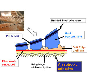
Foot design
- What makes Stickybot unique is its extraordinary design
of foot. Its foot has four segmented toes controlled by single push-pull
cable via two stage differential system. Three different polymers are used
and stiffened by fine fabric to minimize shear stress concentration along
adhesive pads. It took me about three month to finalize design iterating
more than three times. Utilizing high surface energy of poly-urethane, we
can test various adhesive pads on Stickybot feet.
Its interesting curvature of cable path is designed carefully in order to achieve well distributed normal force on the contact area. Since each toes has seven segments, it can conform non flat surfaces. Despite its flexible structure, reliable adhesion requires elaborated force transmission system from cable tension to normal pressure on contact surface. Its desired profile is calculated in such a way shown on the diagram on right.
Basic idea is to create uniform normal pressure that caused by cable angle differentiation. Each segment should have same amount of force assuming constant cable compression force.Differential cable system is employed in order of minimizing number of actuators and force balance among four toes. One equivalent mechanical system is double rocker bogie system.Upper stage differential actuation is rocker and one cable connecting two toes enables lower stage differential system.
iSprawl
- iSprawl is the youngest and fastest sibling of Autonomous version of Sprawl robot family. Prof. Kim joined BDML at the end of this Office of Naval Research project and designed iSprawl for the first creation at Stanford.
iSprawl
- Sprawl robots are designed by inspiration based on study
of cockroaches.
Whereas other sprawl robots utilize pneumatic system, iSprawl is equipped with battery and electric motor and power transmission system that convert rotary motion to reciprocal leg thrust. What most makes iSprawl unique is push-pull cable transmission system. Since Sprawl family turn its orientation by rotation of their leg with respect to hip joint, power transmission path is not fixed. Which is frequent problem in legged robot with centered engine.
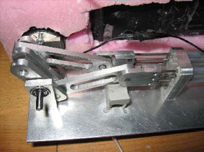
push-pull cable system
- Usage of steel cable as pulling transmission is very common as you can find very easily in bicycle brake and car throttle. iSprawl's cables, however, thrust and pull the legs in high speed (up to 17Hz) without significant energy loss. This enables iSprawl's light and fast movement of legs leading to fast locomotion up to 15 body-lengths/sec (2.3m/s).
- Predecessor of iSprawl, the first sprawl robot that
operates with autonomous power. It uses hydraulic power transmission system.
The idea was to explore hydaulic power transmission to distribute power to
the legs. The tubes contain water and the system works like hydraulic brakes
on a car, with a single master piston and slave pistons at each leg. Aqua
Sprawl is assembled in a bathtub to prevent air bubbles.
After many design iterations, including remachining the original Sprawlita pistons to put in double seals to handle negative pressure on the return stroke, a version of Aqua Sprawl was produced that ran fairly well.Although Aqua Sprawl ran reasonably well, there is a fundamental limitation to the achievable speed because while retracting the pistons, only atmospheric pressure is available. On the other hand, this could be a good design for underwater use!
- Predecessor of iSprawl, the first sprawl robot that
operates with autonomous power. It uses hydraulic power transmission system.
The idea was to explore hydaulic power transmission to distribute power to
the legs. The tubes contain water and the system works like hydraulic brakes
on a car, with a single master piston and slave pistons at each leg. Aqua
Sprawl is assembled in a bathtub to prevent air bubbles.
Swing Leg Retraction
- Swing leg retraction (SLR) is a behavior exhibited by
humans and animals in which the airborne front leg rotates rearward prior to
touchdown. It is hypothesized that SLR enhances running performance of
biological systems, and that we might use SLR to improve the performance of
legged robots. To test these hypotheses, the Biomimetic Robotics Lab
investigates the effects of swing leg retraction on several metrics of
running performance,
- Small disturbance stability and large disturbance rejection
- Touchdown energy losses and overall energetic efficiency
- Potential for injury, as measured by leg forces
- Footing stability, as measured by foot slip distance and horizontal forces
- Spring Loaded Inverted Pendulum (SLIP)
- Biped with massive, telescoping legs
- Biped with massive, telescoping legs and torso
- Biped with massive, kneed legs
- Simulate the effects of a given control law for which swing leg retraction rate can be independently varied to measure running performance
- Optimize periodic trajectories (limit cycles) that maximize a measure of running performance for each of a range of swing leg retraction rates
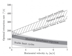
- According to a modified SLIP model, the optimal retraction rate for minimal impact losses (and presumably higher overall energetic efficiency) is generally higher than the optimal retraction rate for maximum stability and disturbance rejection. Moreover, this tradeoff between energetic efficiency and stability becomes increasingly severe as running speed increases.
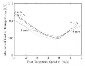
- For simple telescopic-legged robots, increasing swing leg retraction rate (increasing foot tangential speed) results in improved energetic efficiency (lower mechanical cost of transport) up to a point. More specifically, for a range of running speeds, the swing leg retraction rate which minimizes mechanical cost of transport is that required to zero the foot tangential speed (that is, the component of the absolute velocity of the foot at touchdown in the direction perpendicular to the axis of the leg).
Biotensegrity
- Leg’s musculoskeletal system with an adaptive
neuromuscular control employs a synergistic arrangement of bones, muscles,
tendons and ligaments to withstand the high ground reaction forces in a
relatively light structure. For example consider the anatomical arrangement
of the human leg. (See Fig.1) When there is a large load at the
metatarso-phalangeal joints\footnote (ball of the foot) during running, the
ankle (if foot is considered as rigid body as shown in Fig.1c ) would
experience a high moment (roughly 309 N.m for a 70 kg human. Assuming the
length between the ball of the foot and ankle is around 0.15m and the
maximum ground reaction force is three times of weight. However, the ground
reaction force is distributed through the bones, tendons and muscles. As a
results plantar fascia, the Achilles tendon and the gastrocnemius muscle
carry tension and the bones including Metatarsus bones and tibia are loaded
mainly in compression. As the bones have better strength at compression than
tension and tendons and muscles have high strength in tension this
distribution of the loads provide a design which is strong and light. The
tendon also plays an important role in providing necessary compliance and
energy storage. The same principle seen in humans (plantigrades) can be seen
in unglulates (Nail runners as horse, Fig1.b and digitigrades (e.g. cats and
dogs).
In high speed legged robots, while the legs need to withstand ground reaction forces substantially higher than the robot’s weight, minimizing the leg inertia is highly desirable for high speed locomotion. To achieve high speeds, it is essential to obtain high stride frequencies. High stride frequencies require a very short leg protraction time while in the flight phase. In legged robots, high stride frequency can be made possible in two ways, 1) increasing the actuator capacity, and 2) decreasing the leg inertia. The current state of the art in actuator technology precludes increase in actuator capacity without considerably increasing the overall weight. Hence, decreasing the total inertia of the leg structure is more desirable.
Reducing the mass of the legs is the key technique to reduce the leg inertia. However while decreasing the mass, the structural integrity should be maintained, as the legs must withstand high ground impact forces. Therefore designing a high speed legged robot imposes a serious tradeoff between agility (which requires low inertia) and strength of the leg design (which requires bulky structures). This trade off becomes even more critical in distal part of the leg since it contains more complex articulated features. These features are necessary for providing more functions including smooth collision to the ground, elastic energy storage, and added control.
Most current mechanical designs for legged robots deal with this trade-off by using strong and bulky legs made of high strength to weight ratio materials such as Titanium and Aluminum. In addition, it is well known that compliance in leg structures is of high importance in energy efficient running. Using metals lead to very stiff legs making it necessary to introduce other strategies to introduce leg compliance. An alternative way can be adopting the biomimetic solutions found in nature and using available engineering knowledge to provide a feasible engineered solution.
Some of the characteristics of biological systems such as distributing the load, energy storage, using tensile forces having high strength while being light remind us of some pin-jointed structures such as trusses, Tensegrities and cable structures well known in Engineering. Extraction of such design principles and taking advantage of a synergistic arrangement of bones and tendons has several potential benefits: 1) It allows the legged robot designers to use cheaper materials for the leg structures which are also easier and faster to fabricate (e.g. molding plastics), 2) it decreases the weight of the leg structure and thereby reduces the total inertia which has serious implications in energy efficient running, and 3) It contains the elements that can be used as series elastic to provide compliance and energy storage.
The complexity of the foot structure with its neuromuscular control, however, cannot be resembled easily by available engineering material and knowledge. In order to have a feasible passive leg design some of the concepts noticed in the biomechanics of the leg are adopted and a simplified but feasible design based on the available techniques in Engineering is proposed (Fig.2 and Fig.3). Specifically, two methods for decreasing the weight and inertia of the mobile robot’s legs are tried. First, a bio-inspired leg with tendon is devised (See Fig.2). Second, a new bio-inspired foam-core prototyping method for quick and light fabrication of the leg was implemented to make a lighter leg (See Fig.3). 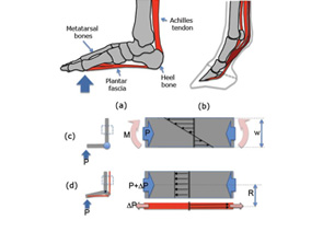
Figure 1
- Figure.1 A synergetic arrangement of bones and tendons ligaments shown in human (a), and horse foot(b). (c), (d) compare the stress distribution between a conventional robotic leg structure and a tendon reinforced leg structure.
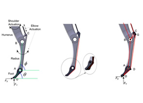
Figure 2
- A potential design of the front leg with torsional stiffness at the foot ankle (Point A) b. A bio-inspired leg design c. The approximate schematic of the equivalent pin-jointed structure of the bio-inspired leg.
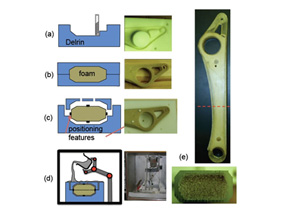
Figure 3
- Fabrication steps for foam-core composite robot structures. (a) mold made by CNC milling, (b) foam-core casted by RTM, (c) positioning disks made of shell material attached to foam part, (d) wireless pouring device inside of the vacuum chamber transfers the resin to the shell mold, (e) complete radius linkage and the cross section
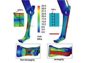
Figure 4
- Figure 4: FEA analysis of the without tendon-design and with tendon design
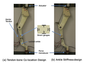
Figure 5
- Experimental setup for measuring stresses on the Radius for the two design concepts