- Offer Profile
- Interdisciplinary way of thinking, experiments and simulation as well as
concentrated efforts of computers have been important methods and tools
since the first years of the institute.
Consequently, the Institute of Applied Mechanics has been integrated into the Department of Mechatronics in 1997. Many of the ongoing research projects with walking machines and humanoid robots are connected closely to medical science and biology.
Robotics and Locomotion
THE INSTITUTE OF APPLIED MECHANICS
- The Institute of Applied Mechanics at the Technical
University of Munich arose from the Institut B of Mechanics by renaming in
2001. The institute was founded by Prof. Kurt Magnus in 1966. The domain of
‘Technical Mechanics’ has been represented in research and higher education
since 1966 continuously.
About 90 doctoral thesis and State doctorate thesis have documented excellent research results, which all are focussed on dynamics, control and optimization of mechanical systems, especially multi-body systems.
In particular, under chair of Prof. Friedrich Pfeiffer, appointed in 1982, the fundamental research has been in strong interaction with applications in automotive industries, space- and aircraft technology, robotics, power train engineering and applications in common mechanical engineering.
Interdisciplinary way of thinking, experiments and simulation as well as concentrated efforts of computers have been important methods and tools since the first years of the institute. Consequently, the Institute of Applied Mechanics has been integrated into the Department of Mechatronics in 1997. Many of the ongoing research projects with walking machines and humanoid robots are connected closely to medical science and biology.
In 2001 Prof. Heinz Ulbrich succeeded Prof. Pfeiffer continuing the successful research activities. 20 PhD students associated with the chair represent its interdisciplinary orientation being mechanical engineers, mathematicians, physicist or electrical engineers. Another key of success is based on the short and open way of communication between scientists, mechanical workshop and electronic lab of our institute.
Being with the Institute of Applied Mechanics, all engineering skills and qualities are supported but challenged, too. A strong connection of research and study is understood to be very important. Thus, the institut offers various courses during your university career, including fundamental lectures on Technical Mechanics as well as specific classes on robotics, machine dynamics or multi-body systems. Finally, student research work via diploma theses has been a vital issue of scientific innovation.
- The Institute of Applied Mechanics at the Technical
University of Munich arose from the Institut B of Mechanics by renaming in
2001. The institute was founded by Prof. Kurt Magnus in 1966. The domain of
‘Technical Mechanics’ has been represented in research and higher education
since 1966 continuously.
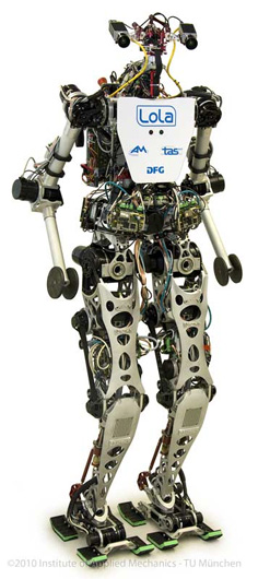
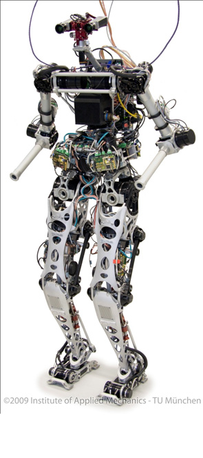
Humanoid Robot "LOLA"
- Institute of Applied Mechanics, Technische Universität
München (AM), Prof. Dr.-Ing. Dr.-Ing. habil. Heinz Ulbrich
Institute for Autonomous Systems Technology, University of the Federal Armed Forces (TAS), Prof. Dr.-Ing. Hans-Joachim Wünsche
Due to their human-like shape and locomotion, humanoid robots are particularly suitable for
applications in the human environment. Future applications include service robotics, entertainment and academic education and research. In spite of great advances in humanoid robot development, their capabilities have not reached human performance yet.
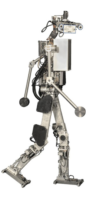
The humanoid walking robot Lola is being developed within the framework of the DFG projectcluster “Natur und Technik intelligenten Laufens” at the Institute of Applied Mechanics at the Technische Universität München (AM). The aim of this research is to realize fast, human-like walking (target speed: 5 km/h).Lola is equipped with a vision system developed in the DFG research project “Towards a general vision system for humanoid robots” (HU-1743/1-1) by the Institute for Autonomous Systems Technology at the University of the Federal Armed Forces (TAS). The newly developed image processing method enables Lola to navigate in an unknown environment.
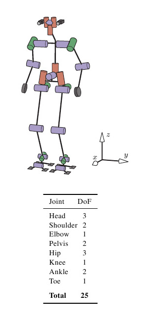
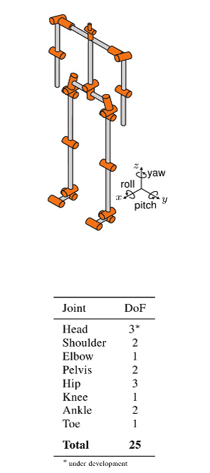
Lola has the proportions of an average, 180 cm tall adult and weighs approximately 60 kg. The structural components design follows a thorough analysis and walking experiments with Johnnie, the humanoid robot previously developed at AM. Lola’s mechanical structure is characterized by an extremely lightweight design and a kinematic configuration with 25 actuated degrees of freedom, allowing for natural and flexible motion patterns. The joints are actuated by modular, multi-sensory servo drives with a high power density. The drives are based on AC servo motors, harmonic drive gears and planetary roller screws, respectively. Unlike humans, the center of mass (CoM) of a biped robot is typically at a level with the hip joint or even below. Since stability increases with higher CoM positions, special emphasis was put on an improved mass distribution of the leg apparatus to achieve good dynamic performance: the mass distribution in the hip-thigh area is significantly improved by employing a roller screw-based linear actuator in the knee joint. The ankle joint is actuated by a parallel mechanism of two linear actuators with the motors mounted on the thigh, next to the hip joint. Thus, a large part of the actuator mass could be shifted close to the hip joint rotational axis, resulting in a highly dynamic behavior of the legs. The dimensioning of structural components is based on a comprehensive multibody simulation model of the robot. For some components with complex multi-axial stress conditions and strict geometric constraints, concept design proposals are determined by topology optimization. Finite element analyses are conducted on all highly loaded parts. Major structural components are designed as aluminum investment castings in order to meet the weight and stiffness targets.
The sensor system supports the implementation of model-based control algorithms. Absolute angular sensors allow the direct measurement of the joint angles, compensating compliance and nonlinearity in the drive mechanisms. A high-precision inertial measurement unit with fiber-optic gyroscopes estimates the orientation and angular velocity of the upper body.The ground reaction forces and moments are measured by a six-axis force/torque sensor. Because commercial six-axis sensors with appropriate measurement ranges are rather bulky and heavyweight, a customized sensor was developed. Due to the highly coupled kinematics and dynamics, central stabilizing control is crucial for a biped robot. From the technological point of view, however, the central control unit can be unloaded from low-level tasks, such as motor control and sensor data acquisition and processing. These tasks are carried out by decentralized controllers, forming an “intelligent” sensor-actuator network with central control of global system dynamics. All controllers are connected by a real-time communication system.
Based on Johnnie’s control system, a hierachical control and trajectory planning system has
been developed. The trajectory planning system generates stable trajectories from a prescribed target walking motion. The reference trajectory planning is improved by a better robot model and an anticipatory calculation of the next steps. A new contact force and CoM trajectory planning method is used. This method runs in real-time giving Lola the ability to react quickly to unexpected events.
Because of even small errors in measurements and models and a vaguely known environment, biped locomotion can not be realized with precalculated trajectories and motor control alone. The planned trajectories are therefore modified based on measured contact forces and torques as well as the inertial orientation and angular velocity of the upper body.
The walking control stabilizes global system dynamics by modifying the planned walking pattern which consists of task space trajectories and contact forces. The modified trajectories are tracked using a hybrid position/force control. The decentral drive controllers form the lowest control layer. Above, the decentral joint angle control layer is located. On the superior layer, the global system dynamics is controlled in workspace. Kinematic redundancies are solved within the workspace control which allows for a simple and effective use of the redundant degrees of freedom. Walking parameters like step length, walking direction or speed can either be set by a human operator or decided autonomously by Lola.
A very important component of autonomous robots is environmental cognition. TAS is particularly interested in visual perception research. In the field of robotics, vision systems get more and more powerful. There are commercial solutions available for quality assurance, monitoring and even navigation systems, e.g. Advanced Driver Assistance Systems like tracking stability. However, these systems are often highly specialized and may not be feasible for a wide variety of applications. Human-like general and flexible cognition is far from technical realization. This is the motivation of the above-mentioned DFG project.
The goal is to develop a general vision system for autonomous mobile robots which can be used in variable situations, like indoor or outdoor scenarios. In the past, robotic demonstrations typically took part in predefined environments. By contrast, the envisioned system can act in any context, thus enabling the robot to walk in user-defined, non simplified surroundings, to learn different objects, search for and recognize them. Therefore a general navigation system with different layers is being developed. The lowest layer realizes a navigation behavior which can be used in a wide field of scenarios and can prevent collisions in a fast and secure way.
But this level is not able to solve complex tasks, like climbing stairs as it recognizes steps primarily as obstacles. These requirements will be handled by higher levels and depend on the existence of specific objects. As soon as the vision system gets to know that a specific cognitive ability can potentially be activated, a transition from the reactive to a higher layer takes place.
The cooperation between layers enables the robot to navigate through any environment. At the same time specific abilities can be used if they are available. By means of the first level — the reactive level — the robot can avoid any natural obstacle while no knowledge of the given objects or environment is necessary. To succeed, a stereo camera rig is used which provides images with a resolution of 5 megapixels.
Depending on the intended action, different information has to be extracted from the input data. In a new approach, the images are dynamically divided into regions of diverse attention, allowing for the execution of complex algorithms only in areas of high informational need. Thereby the system provides high-resolution data processing at the cost of reduced computational load.
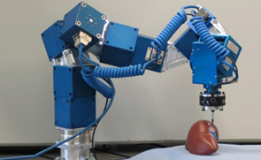
Agricultural robotics
- Project overview
Many site-specific agricultural and forestry tasks, such as cultivating, transplanting, spraying, trimming, selective harvesting, and transportation, could be performed more efficiently if carried out by robotic systems. However, to date, agriculture and forestry robots are still not available, partly due to the complex, and often contradictory, demands for developing such systems. On the one hand, agro-forestry robots must be of reasonable cost, but on the other, they must be able to deal with complex, dynamic, and partly changing tasks. Addressing problems such as continuously changing conditions (e.g., rain and illumination), high variability in both the products (size and shape) and the environment (location and soil properties), the delicate nature of the products, and hostile environmental conditions (e.g. dust, dirt, extreme temperature and humidity) requires advanced sensing, manipulation, and control. Since it is impossible to model a-priori all environments and task conditions, the robot must be able to learn new tasks and new working conditions. The solution to these demands lies in a modular and configurable design that will keep costs to a minimum by applying a basic configuration to a range of agricultural applications. At least a 95% yield rate is necessary for economical feasibility of an agro-forestry robotic system.
Objectives
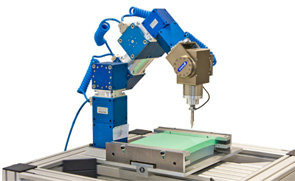
The main objective of CROPS is to develop a highly configurable, modular and clever carrier platform comprising a carrier plus modular parallel manipulators and “intelligent tools” (sensors, algorithms, sprayers, grippers) that can easily be installed onto the carrier and that are capable of adapting to new tasks and conditions. Both the scientific know-how and a number of technological demonstrators will be developed for the agro management of high value crops like greenhouse vegetables, orchard fruits, and grapes for premium wines. The CROPS robotic platform will be capable of site-specific spraying (targeted spraying only on foliage and selected targets) and selective harvesting of fruit (i.e., it will detect the fruit, determine its ripeness, move towards the fruit and grasp it and softly detach it). Another objective of CROPS is to develop techniques for reliable detection and classification of obstacles and other objects to enable successful autonomous navigation and operation of the platform in plantations and forests. The agricultural and forestry applications share many research areas, primarily regarding sensing and learning capabilities.
The project is coordinated by the Wageningen University & Research Center (WUR) in the Netherlands. There are fourteen partners -including the Institute of Applied Mechanics- in the consortium from several European countries as well as Israel and Chile.
The research project Crops – “Intelligent sensing and manipulation for sustainable production and harvesting of high value crops, clever robots for crops” is funded by the European Commission
Projekthomepage: www.crops-robots.eu
Telepresence
- Objective of the
Collaborative Research Centre SFB453 on "High-Fidelity Telepresence and
Teleaction" is to provide the possibility to a human operator of being
present at an unreachable remote environment (telepresence). The operator is
not only passive but also can actively manipulate objects at the remote
location (teleaction). High-Fidelity is achieved, if the human operator can
not distinguish, if his impression and his received feedbacks come from
reality or from a technical device. Besides the visual and auditive
sensorial feedback, the haptic feedback is important for the immersiveness.
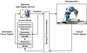
There are effects which are disturbing the telepresence system and thus the immersiveness of the operator. The disturbing effects have to be compensated to ensure the performance of the teleaction. Teleoperations using the internet or satellite connections for communication have to deal with time delays in the transmission. This can result in instabilities of the control loop, consisting of the human operator and the teleoperator.
In the project M7 "Force and Motion Prediction in Teleoperations with Soft Contacts" the time delays are compensated by using prediction. The telepresence system is extended with a motion prediction for the operator's motion and also with a force prediction for the measured forces of the teleoperator.
The force prediction is realized with model-based algorithms which are capable of considering different physical effects such as inertia, friction, rigid and soft body or medical incision. For identification of the model parameters, the measured forces from teleoperator are used. The parameterization is updated at runtime. The evaluation of the force model is done in real-time.
Biped robots with passive elements
- Biped Robots with Elastic and Dissipative Elements
in Terms of Energy Consumption and Stability Considerations
The project „Elastische Mechanismen“ (Elastic Mechanisms, UL 105/32) is part of the DFG package proposal „Natur und Technik intelligenten Laufens“ (Nature and Technology of intelligent walking, DFG PAK 146). The aim of the project is to investigate the influence of elastic and dissipative elements on technical bipedal locomotion. This is archived in cooperation with the Locomotion Laboratory (www.lauflabor.de), University of Jena.
In technical two-legged locomotion two contrary concepts dominate. The first one concerns humanoid robots, with actuated degrees of freedom. For this kind of robot, among other things, the following two topics are important: enhancement of the system stability and reduction of energy consumption, especially when thinking of humanoids working autonomously within a human environment. The second concept concerns robots based on the idea of limit-cycle-walking. The versatility of these robots is very limited. Nevertheless, due to their passive-elastic elements they are able to walk with a very energy efficient gait.
In this project we are investigating a humanoid robot model with adapted actuation. Therefore, we want to take advantage of the benefits from the concept of limit-cycle-walkers, namely passive-elastic elements for energy storage. Thus, the investigated multibody simulation model is based on the topology and geometry of the humanoid robot Johnnie. For the actuation of the robot, different concepts are studied:
The first one is the biologically inspired arrangement, based on the JenaWalker II model from our cooperation partners from the Locomotion Laboratory, University of Jena. For this actuation version several muscle groups are represented by spring-damper elements with linear and progressive characteristics. The model is driven by a dc-motor actuating the thigh only.
For the second concept the joints, which are originally actuated with a drive-chain based on industrial robot, are extended using spring- damper elements. These can be placed serial or parallel to the power-train unit.
By implementing passive elements into the system many questions arise. These concern e.g. a proper set of suitable spring-damper parameters, unknown facts about the robot dynamics, stability and control. Therefore, numerical parameter determination based on optimization as well as shooting methods for the identification of limit cycle motion are applied. The resulting system characteristics are analyzed with respect to cost of transportation and stability considerations.
Theory of Multibody Systems
Fundamental Research
- Keywords: multi-body systems, non-smooth dynamics,
unilateral constraints, set-valued force laws, flexible multi-body systems,
co-simulation
The main objective of the fundamental research at the Institute of Applied Mechanics are methods for the description of multi-body systems (MBS) with non-smooth dynamics. These are systems with closing contacts leading to jumps within the system velocities. Especially for industrial applications with many degrees of freedom and many contacts, efficient and robust methods are currently being developed. The granular media simulation of an hourglass can be seen as a benchmark-problem.
Besides the application of these methods to classical rigid multi-body systems there is a growing interest to extend them for the description of flexible multi-body systems with impacts and constraints. The crucial point is to derive models providing high efficiency and an accurate model description as well as versatile applicability . The classical distinction between finite elements (FE) and MBS is partly left aside to maintain – as far as possible – the advantages of FE-approaches within MBS. An example is given by the rocking rod, which classically is modeled rigid in non-smooth mechanic approaches.
Technical systems are usually composed of different assemblies with different leading physical phenomena but alternating interactions. So far – especially due to lower computational power – the subgroups like e.g. hydraulics and rigid-body dynamics of a chain drive were simulated separately.
To allow for the simulation of the complex over-all dynamics, a co-simulation is performed for the subgroups using own time-integrations and respecting the interactions.
Nonlinear Machine Dynamics
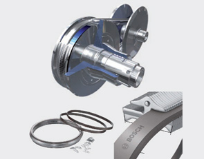
Spatial Dynamics of Pushbelt
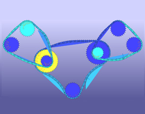
Continuously Variable Transmission and Computational Time Reduction of the MBS Model- In automotive propulsion technology, Continuously
Variable Transmissions (CVT) are an interesting alternative compared to
conventional gear concepts like manual or automatic shift gears. CVTs help
the combustion engine to stay closer to its optimal point of consumption and
efficiency over a wide range of load cases.
Since 2001 the Institute of Applied Mechanics has been working successfully together with Bosch Transmission Technology B.V. (Gasoline Systems – CVT) on developing state-of-the-art multi-body simulation tools for the pushbelt variator of CVTs. The aim is to further optimize the pushbelt by using simulation software to e.g. reduce the fuel consumption.
A number of models and the appropriate software, such as the plane hybrid model or the spatial model, to consider also out-of-plane effects e.g. misalignment, have been designed. The development of mathematical models incorporates all elastic and dynamic effects. The pushbelt is a highly complex multi-body system (MBS), with about 3500 degrees of freedom and 5500 frictionless, frictional as well as uni- and bilateral contacts in the spatial case. The individual bodies are modeled either rigid or as finite elements with large deflections. To derive the equations of motion methods of non-smooth multi-body simulation are used. The resulting differential equations are being integrated with time-stepping methods. The software tool MBSim, which was developed at the institute, is used as program environment.
In the current research project the level of detail of the derived 3D-model is increased and extended by several additional properties. Thereby occurring effects outside of the actual plane of motion can be discussed in more detail. Since especially at high levels of detail the computational time is very large the second objective of this work is to reduce the CPU time. Therefore different reduction methods (e.g. model order reduction, parallel-processing, use of faster sub models) are taken into account. In this context the main difficulty is the transfer of these methods to general, non-smooth flexible multi-body-systems on the one side and to special conditions of the simulation model on the other side.

Medusa
- Reduction of Rotational non uniformity in Automotive
Powertrains Against the background of reducing carbon dioxide emissions and
the fact that the automotive industry is bound by law to realize that, new
drive train concepts have to be developed. Fully electrified drive trains
offer the potential to reduce emissions to a minimum. But very high expenses
for research and development paid by industry and a weak existing
infrastructure, offering broad access to electricity, make other drive train
concepts more attractive. Especially reciprocating engines with a reduced
number of cylinders and smaller engine displacements are interesting, since
the underlying technology is familiar and therefore less expense for
research and development are expected.
In the future automotive industry will still have to offer engines with high power to remain competitive. Both the trend to less cylinders and charged engines as well as reduced engine speeds are changing the excitation characteristics of reciprocating engines dramatically. The results are lower engine orders and higher amplitudes of engine torques.
Considering an automotive powertrain as a mechanical vibration system, lower eigenfrequencies can now become more critical and vibration amplitudes are basically higher. The results are negative influences on the overall vibration behavior and a higher level of structure-born sound. Conventional systems like two mass flywheels or centrifugal pendulums are not capable anymore to compensate such strong excitation levels. Within this research project the focus is on developing innovative concepts offering new possibilities to reduce vibrations in future powertrains. From understanding the phenomenology of vibrations through optimizing system performance in presence of dissipation mechanisms modeling and simulation under defined boundary conditions has to be done iteratively.
Modeling and Optimization of Machine Processes
- Interactions between machine structures and manufacturing
processes, such as vibrations due to unsteady cutting, limit the process
flow. With a detailed prediction of these interactions it is possible to
optimize operation charts, machine parameters, path parameters and further
details. The goal of the project "`Parametric modeling, prediction and
optimization of interaction between machining process and structure using
multibody systems and implicit filtering"', a research project of the
priority program 1180, financed by the DFG (German Research Foundation), is
to build a simulation model of an existing turning lathe and to optimize the
manufacturing process. The project is a collaboration with the Institute for
Machine Tools and Industrial Management (iwb), Technische Universität
München.
The optimization is based on models of the machine and the cutting process. One task is to build a
model of the machine and to formulate the coupling between the specific models of the machine and the process. The cutting model is formulated in a way that allows the separation of chisel and work piece during the work process. This is realized by a modified unilateral contact augmented by a cutting model from IWB. The cutting model is validated with machining experiments.
The developed simulation model is used to optimize the operation charts. The used optimization algorithm needs a goal function to rate the process. Therefore, different goal functions are developed and investigated during this project. The simulation results are used to calculate the new surface and its characteristics and assessment criteria of the machining quality are obtained by both of them. A facing process is chosen as a test operation for the optimization. The optimization tool detects ideal parameters for the operation with respect to the dynamic limits of the working machine. With physical experiments the results are verified.
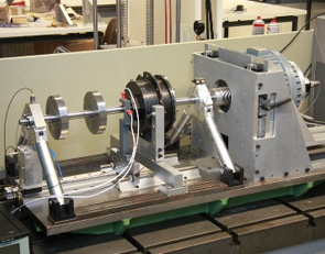
Model-based Monitoring in rotor systems
- A new technique for model-based monitoring in rotor
systems is in development. This method enables a detailed automatic
identification of different types of defects. The developed concept consists
of an automated multi-stage process for detailed defect identification.
Phase A: Observation
During operation of the rotor system sensor signals like bearing accelerations, rotor deflections or control currents are observed permanently. Once a sensor signal leaves the normal range an unknown defect is indicated immediately and a measurement is recorded. The measured data are transferred to phase B, wherewith phase B is activated.
Phase B: Identification of failure
The aim of this phase is to get signal-based as much information as possible about the occurred defect. The measured data is analyzed in time as well as in frequency domain to allocate a specific type of damage to the measurement. Mostly the signal-based identification is not detailed enough. Thus, the still unknown defect parameters (e.g. location, dimension etc.) are identified by the optimization of the alignment of simulation and measurement. Depending on the detected defect a cost function is formulated and an adequate optimization algorithm is chosen and phase C is activated.
Phase C: Simulation and optimization
For phase C a detailed simulation model of the rotor system extended by a modeling of the investigated defects is essential. After the identification of a failure in phase B the defect parameters of other defects in the simulation model are set to the undamaged value. Only the still unknown parameters stay variable. The optimization algorithm and the cost function are allocated to the occurred defect and deposited in a defect databank. After the optimization process the unknown fault parameters are determined and an aligned simulation of the damaged system is available.
Phase D: Output and storage
In the last step the identified defect, the location and the dimension of the defect is displayed. The analyzed measurement and the simulation of the defect are saved to investigate the influence and to observe the progress of the defect. A modular test rig has been developed to verify the simulation and to prove this monitoring technique. Therewith several defects with different intensities can be replicated.
Optimization of Control Assembly in Friction and Acoustics
- Combustion engines are required to reduce noise and
exhaust emission while simultaneously keeping or increasing their
performance. To achieve these goals, optimizing the components and
assemblies is a key task.
Besides the computation of the dynamic quantities within the system, the simulation of friction demands for suitable models under changing physical boundary conditions, such as the temperature, the viscosity of the operating material and the external excitation. Also, the numerical treatment of the discontinuous dynamics due to the high-frequent oscillations is challenging.
Concerning the acoustic simulation, it is not suitable to simulate the entire transfer path from the engine to the passenger. Instead, interfaces like bearing zones must be identified, serving as backup mechanical quantities and allowing for similar evaluation.
The optimization process of the system comprises friction and acoustics. Due to the large number of parameters and the complexity of the system, methods of reducing computing time play an important role. Possible approaches are suitable evolutionary algorithms, using neural networks and arallelizing computing processes.
FORBIAS
- Researchers of the Institute of Applied Mechanics work
together with the Institute of Real-Time Computer Systems and the Bernstein
Center for Computational Neuroscience of the Ludwig-Maximilian-University
Munich in the Research Cooperation for Bioanalogical Assistant Systems (FORBIAS).
The aim is to technically imitate what is called the vestibule-ocular reflex
in biology. This reflex enables human beings to get a static impression of
the environment although head and body may be in motion.
In one sub-project of the research cooperation, an inertial measurement unit inspired by the human vestibular organ is developed. The sensor captures motion in all 6 degrees-of-freedom of translation and rotation. In an intelligent algorithm, these signals are fused for the derivation of orientation in space. By using the feedback of image processing, equivalent to the human eye and the visual cortex, the sensor is calibrated online. Adaptive approaches of interference cancellation in combination with modern decorrelation control lead to excellent results.
In a further sub-project systems are being developed that move the gaze direction of cameras. These systems serve to compensate for motions measured by the inertial measurement unit in order to realize technical gaze stabilization. The actuator system has to be capable of reaching dynamic properties comparable to the human oculomotoric system. The development of extremely fast motion devices as described above requires the analysis of existing systems as well as mechanical examinations and control optimization. Besides simulations of certain interesting subareas of the system hardware experiments are being performed using real-time digital signal processing.
Thus performance characteristics as well as different specific effects can be investigated. Camera motion devices can be used in many different applications. A wearable head camera system that looks where the user looks is one example. Here a video-oculograph systems track the user’s eye motions and send motion commands to the actuators which align the camera parallel to the user’s current gaze direction. A system like that can be used for the recording of special film sequences or for documentation purposes, for example during surgery.
A camera stabilized by an inertial measurement unit is a base for driver assistance systems based on image processing or to support pilotes during the landing approach of aircrafts or helicopters.
Mechatronics
Actuators
- In all fields of modern engineering there is a demand
for powerful and compact high-performance actuators, being the crucial
connecting link between information processing and operation process.
Recently, huge advances in mechatronics pushed improvements of old actuator
concepts as well as the development of new innovative principles. One major
goal of actuator research has been performance enhancement, so far. New
investigations tend to focus more on reducing volume and power consumption
in terms of operational efficiency.
Intensive long-term research activities on actuator technology at the Lehrstuhl für Angewandte Mechanik have established a profound experience in following fields:
- magnetic technology (electromagnetic reluctance force actuators, electrodynamic shaker, ref. Fig. 1);
- hydraulics (high-bandwidth hydraulic actuator, ref. Fig. 2);
- shape memory actuator (bio-analogue finger, ref. Fig 3);
- piezo actuator.
Current research projects deal with the electromagnetic shaker (Fig. 1) and hydraulic actuator (Fig. 2), both being designed to meet industrial needs and setting a benchmark in performance-volume-ratio.
Their key data below outlines the capabilities of high actuation forces and high bandwidth at low volume:
- Electromagnetic Linear-Actuator (size-dependent): stroke (2…5) mm, force vector (1…3) kN, bandwidth DC…200 Hz;
- Hydraulic Short-stroke Actuator: stroke 1 mm, force vector 6 kN, bandwidth DC…150 Hz.
Another area of research is to improve controller robustness for the actuation system comprising “actuator, driving circuitry and test element” respecting industrial aspects as operational security and costs.
Finally, each actuator must reproduce given acceleration signals with high correlation, e.g. to act as a shaker system in test rigs for squeak and rattle. A couple of key issues have to be considered to achieve this goal:
- Control theory: state space control, cascaded control, forward linearization;
- Driving circuitry and periphery: digital signal processing und visualisation, digital power amplifier >1 kW, sensors, servo valves.
Future research will concentrate mainly on electromagnetic phenomena. The advent of high-performance materials (rare earth permanent magnets, soft alloys) offers an enormous potential for efficient application of magnetic forces. In recent developments, attractions forces controlled by coils played a huge part in the electromagnetic field (reluctance force drives, e.g. Transrapid) as well as in electrodynamic applications (lorentz-force type actuators, e.g. electric motor). The inevitable advantages of those systems are contrasted by disadvantages, too, e.g. instability or ohmic losses. Investigations on the Lehrstuhl für Angewandte Mechanik try to present alternative ways for actuation principles:
- Coil-less magnetic actuator: Magnetic flux control without coils and currents;
- Magnetic repulsion forces: Eddy-current induced repulsion forces on fast-moving objects (principle of induction motor). 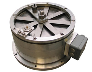
Figure 1: Electromagnetic linear actuator
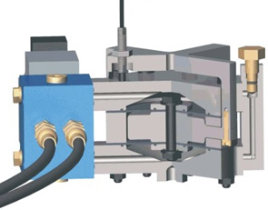
Figure 2: Hydraulic short-stroke actuator
Compact High Dynamic Camera Orientation Systems
- Images acquired from a first person's perspective can
be used to estimate the user's intention. Required high quality images can
be retrieved when continuously aligning a camera with the human gaze. The
human vestibulo-ocular and optokinetic reflexes automatically stabilize the
human eye, even under dynamic conditions. Such an approach, however,
requires camera orientation systems which are able to reproduce the high
dynamic movements of the human oculomotor system, while at the same time
providing a small and lightweight design. In this project, parallel
kinematic manipulators, driven by ultrasonic piezo-actuators, with two and
three rotational degrees-of-freedom are developed. Besides kinematic, also
dynamic models are calculated and used to optimize the workspace/package
ratio and to estimate force and velocity output capabilities. Furthermore a
series of control strategies are investigated. Prototypes of the designed
camera orientation systems are developed and integrated into different
application scenarios.
The described research activities are embedded in the interdisciplinary cluster of excellence “Cognition for Technical Systems – CoTeSys”. The aim of the work is to develop and control compact high dynamic camera orientation systems which are specifically designed for the needs of the CoTeSys projects "Action recognition from look-ahead fixations of objects in space with self-calibrating gaze control of head-mounted stereo cameras'' (project #106) and "EyeSeeCam: Natural Visual Exploration and Interaction in Humans and Robots'' (project #414). Furthermore, the camera orientation systems are also adapted to other application scenarios (remote eye tracker, active vision system for humanoid robots as well as eye-related Wizard-of-Oz scenarios) in collaboration with project partners from the Chair for Clinical Neurosciences, LMU Munich, the Institute for Human-Machine Communication, TUM, and the Institute for Cognitive Systems, TUM, within the CoTeSys cluster. 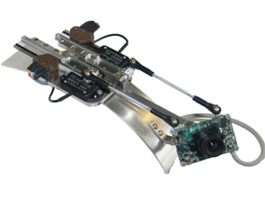
Camera orientation system with two degrees-of-freedom
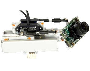
Camera orientation system with two degrees-of-freedom
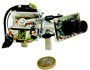
Camera orientation system with three degrees-of-freedom
Concluded Projects
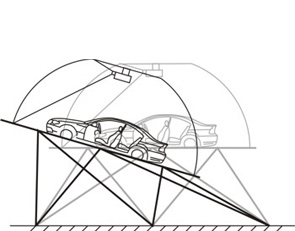
Motion Cueing Algorithms - Driving Simulators
- More and more car manufacturers possess their own driving
simulators, which are under continuous development. They should allow the
driver to dive into the virtual reality and to make it possible to simulate
real world driving experiences.
The optical illusion of the driving scenes is created with a graphic system for visual display, which consists of projectors, high performance computers and a big screen. With this equipment, streets, cities and autobahns are created.
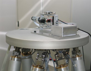
To generate the movements, especially the accelerations of the simulated vehicle, a motion platform is necessary. Usually Stewart-Gough Platforms are being employed for flight as well as for driving simulators. These parallel robots are assembled of six electromagnetic or hydraulic linear actuators, which connect the ground with an upper platform. The advantage of such a system is its ability to conduct movements in all six degrees of freedom (3 translational dof, 3 rotational dof). Mounted on the upper platform is the replication of a car interior, the mock-up. The passenger, sitting inside the mock-up, steers the simulated vehicle like in a normal car by the steering wheel, break and acceleration pedal.
There is a wide range of possible applications for driving simulation. It is used to analyse driving behaviour in risky situations, or to test new control elements, for example. Further topics are:
· Reduction of developing times
· Evaluation and tuning of driver assistant systems
· Checking safety concepts
· Human factors
· Handling of information systems
· Driving behaviour with distractions
· Human perceptions
· Etc.
Project objective: Optimization of the movement behaviour of the dynamic driving simulator at BMW
Several motion cueing algorithms have been developed and designed, especially for the use in driving simulations. Technical limitations and the human motion perception have been taken into consideration. The driving simulator at BMW has being used for implementation and testing of the algorithms. At the end of the project, the simulator was able to present enhanced driving dynamics to the driver.
Reduction of Contact Forces of a Rubbing Rotor by Active Control
- The control of rubbing phenomena in rotating machinery is
of practical interest for the prevention of structural damage since there is
the possibility of serious failures up to complete destruction of the system
if the impact forces are not taken under control.
Rotor-to-stator rubbing in rotating machinery is a secondary malfunction resulting from a primary cause which perturbs the machine operational conditions, such as unbalance or assembly misalignments. In rotating machines, increased efficiency is often achieved by tightening operation clearances, and so, if the machine is not operating under normal conditions, the stationary and rotating elements are in danger of coming in contact. Auxiliary bearings or back up bearings are used in rotor systems to prevent direct contact between rotor and casing when the rotor response is too large.
In this research project a new concept to reduce the severeness of rubbing phenomena in rotating machinery is investigated. Therefore a control concept for an active auxiliary bearing has been developed. The auxiliary bearing is attached to the foundation via two powerful electromagnetic actuators, which have been developed at the Institute of Applied Mechanics, TU Munich.
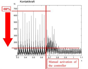
A two phase feedback control, which has been designed using numerical simulations, assures a smooth transition from the state of free rotor motion to a permanent contact in the desired state ‘full annular rub’. The first experimental results show, that the applied control concept leads already to a drastic reduction of the impact forces and a stabilization of the rotor system.
For industrial application the activation and deactivation of the control system can be operated fully automatically. The developed control of the auxiliary bearing is able to reduce the load and the noise of the whole system significantly, which increases its life-span and of course its safety as well.
The future research work will focus on the development of an adaptive control which is able to compensate measurement errors. In addition, there are still uncertainties relating to the friction coefficient, which has a great influence on the process of rubbing. The measurements will also be expanded on supercritical rotors. Furthermore there is the possibility to expand the control system to take influence on torsional vibrations.
Biped Robot JOHNNIE
- Institute of Applied Mechanics, Technische Universität
München (AM), Prof. Dr.-Ing., Dr.-Ing. E.h., Dr. h.c. mult. (i. R.) Emeritus
of Excellence Friedrich Pfeiffer
Institute of Automatic Control Engineering, Technische Universität München (LSR), Univ.-Prof. Dr.-Ing. Dr.-Ing. h.c. Günther Schmidt
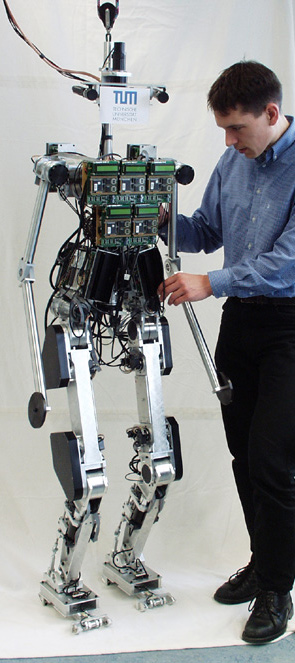
People have been fascinated by walking machines for a long time. A growing number of research groups is addressing the problem of realizing biped robots. Large advances in the development of actuators, sensors and particularly computers allow for the realization of more and more sophisticated walking robots. Within the framework of the DFG “Priority Program Autonomous Walking”, the JOHNNIE-project developed and build an autonomous biped walking robot. The main objective was to realize an anthropomorphic walking machine with a human-like, dynamically stable gait. The robot is able to walk on even and uneven ground and around curves. Further, a jogging motion is planed, which is characterized by short ballistic phases where both feet are not in contact with the ground. The robot is autonomous in terms of actuators, sensors and computational power, while the energy is supplied by a cable.
JOHNNIE's structure resembles the human locomotor apparatus and has a total of 17 actively driven joints. The overall weight is about 49kg, the height is 1,80m. Each leg incorporates six driven joints. Three of them are located in the hip, one actuates the knee and another two drive the ankle joint (pitch and roll). Furthermore, the upper body is equipped with a rotational degree of freedom about the body's vertical axis. Two arms with two DoFs each are employed to compensate the overall momentum about the body vertical axis. The joints are driven by brush DC-motors in combination with lightweight gears. Joint angles and velocities are measured by incremental encoders. Further, two six-axis force sensors in the feet measure the ground reaction forces. An inertial measurement unit consisting of a three-axis accelerometer and three gyroscope sensors determines the spacial orientation of the upper body. A PCI-I/O-board interfaces the main computer (Pentium IV 2,8GHz) with the sensors and motor drivers. The control algorithms run on the PC as RT-Linux kernel modules.
JOHNNIE's control system is subdivided into three layers. The top layer handles the computation of the trajectories and switches between different walking patterns and phases of gait. One step is composed of various different phases such as the stance and swing phases. For each of these phases, the robot's motion is computed such that the planned trajectory does not lead to a tilt or lift off of the stance foot. On the second level the system dynamics are controlled, so that the robot can keep its balance. Even when the reference trajectories are ideal, the upper body may deviate from its reference due to ground inclination or external forces. The inclination of the robot is measured with the inertial measurement unit and the trajectories are adapted such that the upper body is stabilized in an upright position.
The balancing control uses a reduced system model which can be computed in real time. Simultaneously a force-torque control ensures that the feet do not tilt, which is necessary in order to maintain controllability.The resulting motion of the robot is mapped onto the joint angles, which are controlled on the lowest layer. The position, velocity and acceleration of each joint is controlled by a PID controller with friction observer.
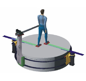
Cyberwalk: Omnidirectional belt array platform
- The CyberWalk project follows a holistic approach
covering science, technology and application by integrating the necessary
blend of cognitive understanding with high fidelity technological
development, to end up with a fully immersive showcase.
Despite recent improvements in Virtual Reality technology it is at present still impossible to physically walk through virtual environments. In this project our goal is to significantly advance the scientific and technological stateof-the-art by enabling quasi-natural, unconstrained, and omni-directional walking in virtual worlds. To achieve this visionary goal we follow a holistic approach that unites science, technology and applications, CyberWalk will develop a completely novel concept for a high-fidelity omni-directional treadmill, named CyberCarpet.
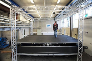
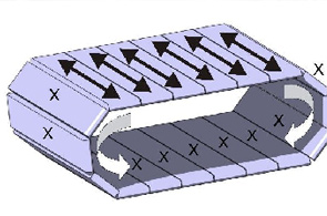
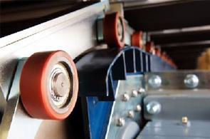
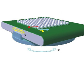
The cyberwalk is an omidirectional motion platform which enables the compensation of any motion of the user which stands on it.Basically the platform consists of several belts which form an endless torus. The belts can be actuated and generate motion in one direction (X), the whole torus can rotate and generates motion an a second direction (Y). As the two motions can be controlled independently, any resulting motion can be generated to recenter a person.
The actual implementation offers 3.5 to 4.6 meters of walking space and will be sized up to 5.5 times 4.6 meters by december 07 speeding up to 2 m/s (person starts jogging). As far as known this is the lagest and fastest implementation wordlwide at the moment (Stated Oct 07).
The plaform can be easily sized up by its modularity. The theoretical span is almost unlimited by an innovative construction (patend pending). As size matters with regard to the maximum allowable accelerations on a human on the platform, this implementation can be considered as a major breakthough in the history of motion platform construction.Fields of application:
- The "holodeck": The user is equipped with a Head Mounted Device (HMD) which shows the virtual reality. The HMD is trackes with a motion tracking system, on the one hand to generate the video data for the stereo vision of the HMD, on the other side to calculate the deviation of the user from the platforms center. This deviation is used to recenter the user. By respecting acceleration limitations and other restrictions, this process will not be noticed by the user. Many different applications are possible, from a walk to a new designed urban area to the research of an order picking process in an innovative environment. Within this project, it is possible to walk around in the ancient Pompeij using the city engine.
Cybercarpet: Ball Array platform
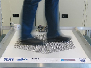
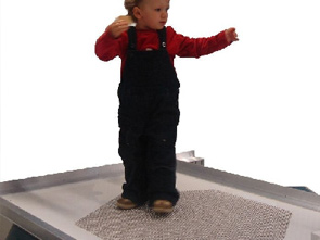
- The Cybercarpet is a small scale implementation of a
ball bearing platform. The basic principle has been outlined in patent
applications and could also be seen in the hollywood movie "Disclosure"
(1994) in an artistic representation.
We were able to implement the platform in a way that it is now able to really walk on the platform and execute perceptual studies about the ball array and its behaviour. Moreover a small test vehicle was built to carry out downscaled trajectories which were recorded via GPS and accelerometers.
The platform is able to speed up to 2m/s on the belt system and 2 rad/s on the rotational DOF, including a walking area of approximately 0,8m in a hexagonal shape. Up to now (Oct 07) the fastet and biggest implementation of this platform type.
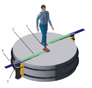
Foot Following Device
- Many foot following devices were published in the
recent years, many prototypes have been built. The thing which lacks these
devices is the possibility to make sudden turns.
The proposed device consists of of three degrees of freedom (1-3) per foot which provide the foot following capabilities. Moreover, a fourth degree of freedom (4) is added to rotate the whole system in case of curved walking or turns.