UL evaluates Potential Induced Degradation (PID) of PV Modules
Utility Scale PV Power Plants operate at high system voltages ranging from 500 Vdc to 1000 Vdc. It has been observed that this high potential can lead to or accelerate module degradation through multiple factors. Such factors may result in conditions such as potential induced degradation, polarization, electrolytic corrosion, and electrochemical corrosion. These factors are prevalent in wet or damp environments, such as morning dew or rain, as well as in those subject to module soiling with conductive, acidic, caustic, or ionic materials. When field installed, crystalline silicon modules may degrade in positive as well as negative polarity which is dependent on cell construction, module production processes and materials and overall design.
PV module manufacturers have found the data from this test beneficial in their reliability efforts for warranty and other financial analysis purposes. Proving that a PV module is not susceptible to PID by conducting a scientifically proven and repeatable test at a third party lab improves bankability and credibility

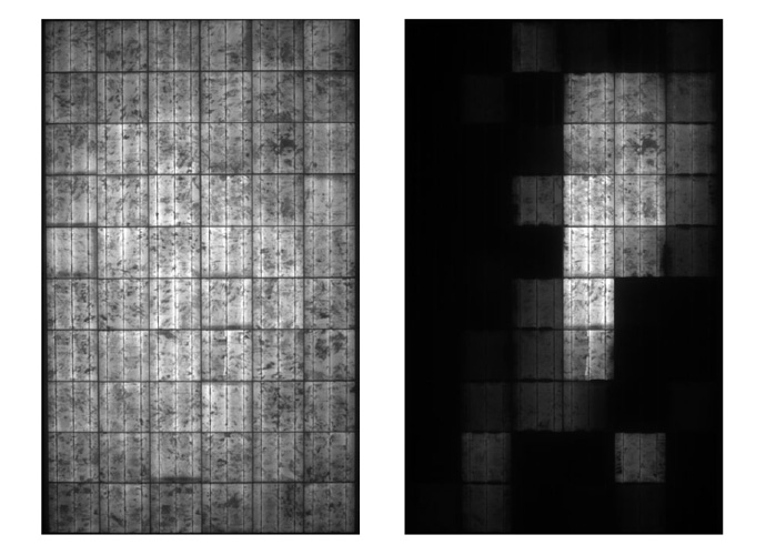
EL images before (left) and after (right) the PID test of
a standard multi crystalline PV module. Dark cells represent PID susceptible cells.
UL Test Program for PID effect on PV Modules
UL offers a scientifically proven laboratory test program to evaluate the effects of stress of both polarities for modules based upon the manufacturer’s specifications. Objectives:
1. Perform a repeatable test which evaluates the crystalline silicon PV module’s performance against system voltage stress
2. Screen for PID susceptibility of c-Si solar cells in a given module package (glass, encapsulant) with related PID safeguards bypassed
3. Perform additional tests and analysis to further expose PID susceptibility and verify module safety
4. Perform comparative analysis of PV mIn addition, the installation instructions, grounding and mounting means as specified by the module manufacturer (if any) shall also be provided.odules for PID susceptibility
Two representative and identical samples each contain at least 60 cells for each polarity of the system voltage that is specified or allowed in the module documentation and one control sample shall be provided. The sample modules shall be constructed with the same process and design as the model type to be evaluated. The sample modules shall contain all components including cells, encapsulant, backsheet, glass, and frame of the same manufacturing process (process tool design and process conditions) as the model type to be evaluated.

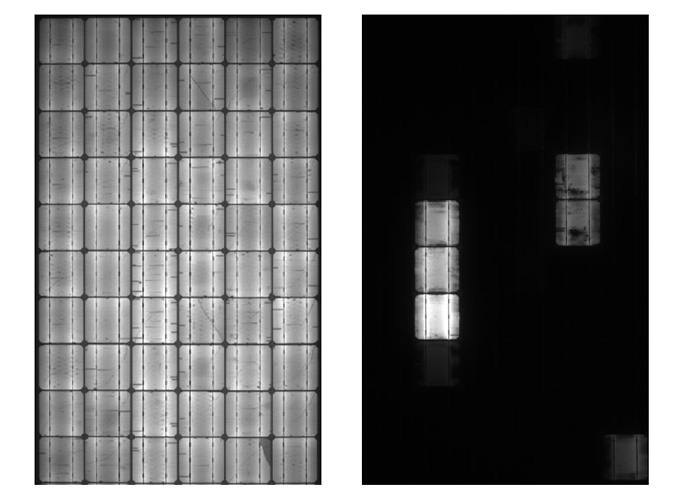
Before (left) and after (right) images of a monocrystalline PV module.
In addition, the installation instructions, grounding and mounting means as specified by the module manufacturer (if any) shall also be provided.
UL Test Setup
The following bullet points highlight the test conditions:
• Module temperature during the test 25°C +/-1K • Module front is covered the Aluminum foil and an additional conductive fluid
• Module is positioned horizontally during the test
• Applied DC potential: System voltage (usually 1000V) or otherwise specified
• Minimum test time: 168h + 168h = 336h (2 weeks) Performance evaluation: The following measurements are performed at specified stages of the PID test:
• Power determination at 1000W/m2 (UL 61215 Clause 10.2) and 200W/m2 (UL 61215 Clause 10.7)
• EL-imaging • Safety related tests including the insulation test (UL 61215 Clause 10.3) and wet-leakage test (UL 61215 Clause 10.15)

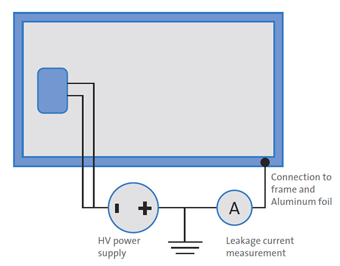
Schematically setup of the PID test for standard p-type c-Si PV modules
UL’s PID susceptibility evaluation
UL will investigate the power loss at 1000W/m2 (STC) and 200W/m2 (low light). Potential induced degradation is a result of shunting the solar cells. Low light behavior of the PV module is critical to performance. Therefore, UL will use 1000W/m2 and 200W/m2 as susceptible criteria.
A PV module is called PID susceptible if one of the following applies:
• ΔPmpp > 5% after 168h at 1000W/m2 and 200W/m2 and
• ΔPmpp > 10% after 336h at 1000W/m2 and 200W/m2
A PV module is not susceptible to PID if at both irradiance levels and after both stages the module fulfills the power loss criteria of less than 5% and 10% after 168h and 336h, respectively.
The Results
The following show measurements taken from PID susceptible PV modules to illustrate the effect and severity of PID.

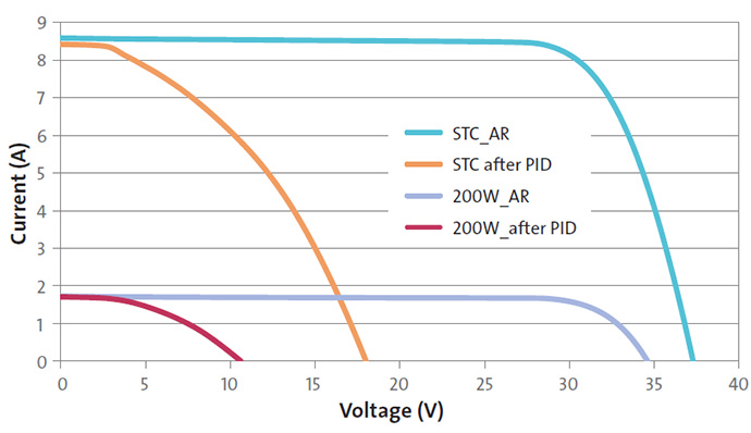
Sample IV curves before and after PID testing collected at 1000W/m2 and 200W/m2. The IV curve change is more severe at 200W/m2 compared to 1000W/m2 and demonstrates the influence of PID on the low light behavior on module performance
For further information visit: www.ul.com
News Categories
- » NEWS HOME
- » Automation & Robotics
- » Industry 4.0
- » Material Handling
- » Sensors
- » Quality & Testing
- » Machine Vision
- » Laser & Optics
- » Metalworking
- » Motion Control & Drives
- » Hydraulics & Pneumatics
- » Process Industry
- » Renewable Energy
- » Agriculture
- » Home & Office Furniture
- » Environmental Tech


